
Method and structure for self healing cracks in underfill material between an I/C chip and a substrate bonded together with solder balls

a technology of underfill material and crack propagation, which is applied in the field of crack propagation and crack propagation in underfill material between an i/c chip and a substrate, and can solve problems such as cracks that may be developed, cracks that will increase in length, and electrical failures

Inactive Publication Date: 2006-05-16
IBM CORP
View PDF10 Cites 26 Cited by
  • Summary
  • Abstract
  • Description
  • Claims
  • Application Information

AI Technical Summary

Benefits of technology

The patent describes a method for repairing cracks in a material used to bond chips to a substrate. The method involves dispersing small capsules containing a curable adhesive in the material. When a crack forms, the capsules rupture and release the adhesive, which then bonds the edges of the crack together. This can prevent the crack from spreading and causing damage to the chip or substrate. The method can be used to improve the reliability and durability of electronic devices.

Problems solved by technology

The cracking of underfill material that encapsulates solder balls joining an I / C chip to a substrate often leads to electrical failures.
These cracks may be developed during assembly or during thermal cycling (either reliability testing or field cycles).
These cracks will increase in length as the electronic package experiences an increasing number of thermal cycles.
The propagation of these cracks has been known to cause electrical fails in copper lines and C4 joints.
However, normal variability in assembly conditions may cause cracks to be formed.
As electronic packages are exposed to higher temperatures and stress in lead-free solder applications, the opportunity to cause cracks increases.

Method used


Image

  • Method and structure for self healing cracks in underfill material between an I/C chip and a substrate bonded together with solder balls
  • Method and structure for self healing cracks in underfill material between an I/C chip and a substrate bonded together with solder balls

Examples


Embodiment Construction

)

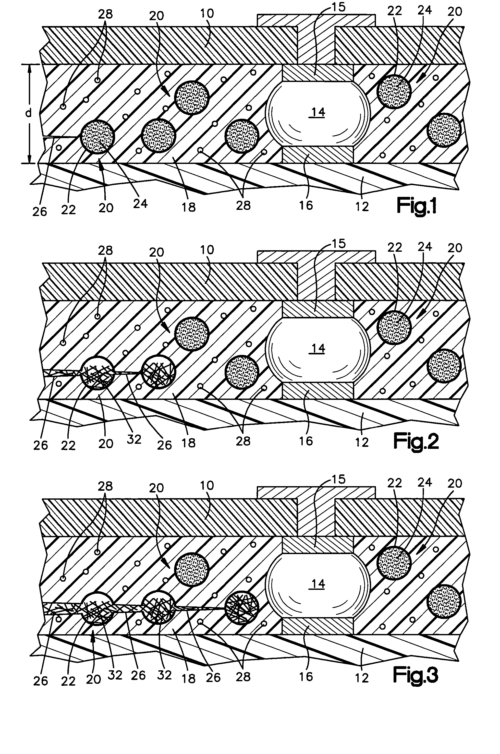
[0006]According to the present invention, a method and structure for self healing cracks that propagate in an underfill material surrounding solder ball or C4 connections connecting an I / C chip to a circuitized structure is provided. FIGS. 1–3 show diagrammatically the structure and the propagation of a crack, and how the invention self heals the propagating crack with a thermosetting adhesive that is cured in situ. (These figures are similar to those shown in the Nature Magazine article cited infra.)

[0007]Referring now to FIG. 1, the structure includes an I / C chip 10 mounted to a circuitized substrate 12 by conventional solder ball or C4 joints 14 between pads 15 on chip 10 and pads 16 on substrate 12. This type of structure need not be described further. The distance d between the chip 10 and substrate 12 is typically about 100 microns. An underfill material 18 is disposed between the chip 10 and substrate 12 surrounding the C4 joints 14. Conventionally, the underfill material is...


PUM

PropertyMeasurementUnit
diameteraaaaaaaaaa
diameteraaaaaaaaaa
distanceaaaaaaaaaa

Abstract

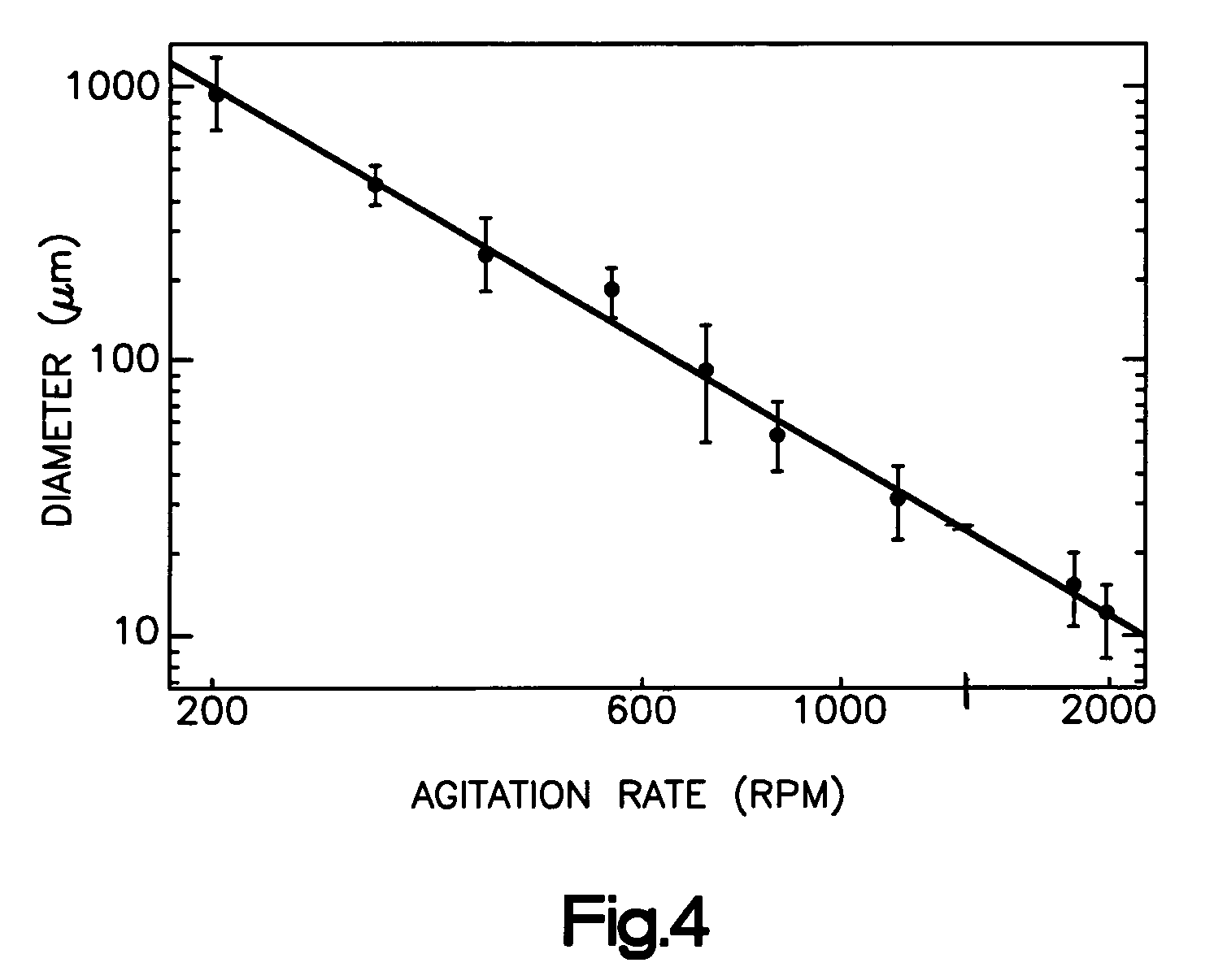
A method of self-healing cracks in a cured epoxy base underfill material between an I / C chip and a substrate is provided. A plurality of capsules is dispersed in the epoxy base. Each capsule has a curable thermosetting adhesive encapsulated in a rupturable shell to disperse the thermosetting adhesive in a crack in the epoxy base when the shell ruptures. Each capsule is less than 25 microns in diameter. A curing agent that will cause a reaction of the thermosetting adhesive on contact is dispersed in the epoxy to form a cured adhesive in a crack in said epoxy base. The shell will rupture when encountering a crack being propagated in the underfill material, which will at least partially fill the crack with the adhesive, and cure the adhesive with the curing agent to bond the edges of the crack together. The invention also includes the structure for crack self-healing.

Description

FIELD OF THE INVENTION[0001]The invention generally relates to preventing the deleterious effects of cracking and crack propagation in underfill material between an I / C chip and a substrate, wherein the chip is joined to the substrate by solder balls, sometimes referred to as C4 joints, and more particularly to healing of cracks that form in underfill material between an I / C chip and a substrate with solder ball bonds.BACKGROUND OF THE INVENTION[0002]The cracking of underfill material that encapsulates solder balls joining an I / C chip to a substrate often leads to electrical failures. These cracks may be developed during assembly or during thermal cycling (either reliability testing or field cycles). These cracks will increase in length as the electronic package experiences an increasing number of thermal cycles. The propagation of these cracks has been known to cause electrical fails in copper lines and C4 joints. Typically, the solution to this problem is to avoid generating crack...

Claims


Application Information

Patent Timeline
Patent Type & Authority Patents(United States)
IPC IPC(8): C08K9/10C08L63/00H01L21/56H01L21/58C08L61/24C08L65/00H01L21/54H01L23/18H01L23/28H01L23/29H05K3/22H05K3/30
CPCH05K3/305H01L23/293H01L21/563C08L63/00H01L2224/73203H05K3/225H05K2201/10674H05K2201/10977C08L65/00C08L61/24H05K2203/1163C08L2666/02Y02P70/50
Inventor THIEL, GEORGE H.
Owner IBM CORP
Learn More