Method and apparatus for adjustment and automatic readjustment of the lamp in a microscope

a technology of automatic adjustment and adjustment, which is applied in the direction of light and heating apparatus, scientific instruments, anti-hunting elements, etc., can solve the problems of poor homogeneity of illumination field, use of such lamps, and lamp wear

Active Publication Date: 2006-05-16
CARL ZEISS MICROSCOPY GMBH
View PDF3 Cites 14 Cited by
  • Summary
  • Abstract
  • Description
  • Claims
  • Application Information

AI Technical Summary

Benefits of technology

[0012]It is the primary object of the present invention to develop a solution by which it is possible for the user to adjust the lamp with the fewest possible degrees of freedom and without a basic knowledge of adjustment when assembling the light and also during its operation.

Problems solved by technology

There are essentially two disadvantages to the use of such lamps.
For one, the lamps that are used are subject to wear which expresses itself with increasing lighting hours in an increased electrode gap due to erosion.
As a result, the intensity centroid of the illumination light moves out of the focus position in the optical axis so that the homogeneity of the illumination field worsens in addition.
The other disadvantage consists in that the gas discharge lamps that are used have large mechanical tolerances due to their method of manufacture.
However, the arrangements mentioned above have the disadvantage that the sequence of adjustment steps to be carried out is very complex due to the many degrees of freedom and these adjustment steps require a certain basic knowledge of adjustment in order to achieve optimal adjustments.

Method used


Image

  • Method and apparatus for adjustment and automatic readjustment of the lamp in a microscope
  • Method and apparatus for adjustment and automatic readjustment of the lamp in a microscope
  • Method and apparatus for adjustment and automatic readjustment of the lamp in a microscope

Examples


Embodiment Construction

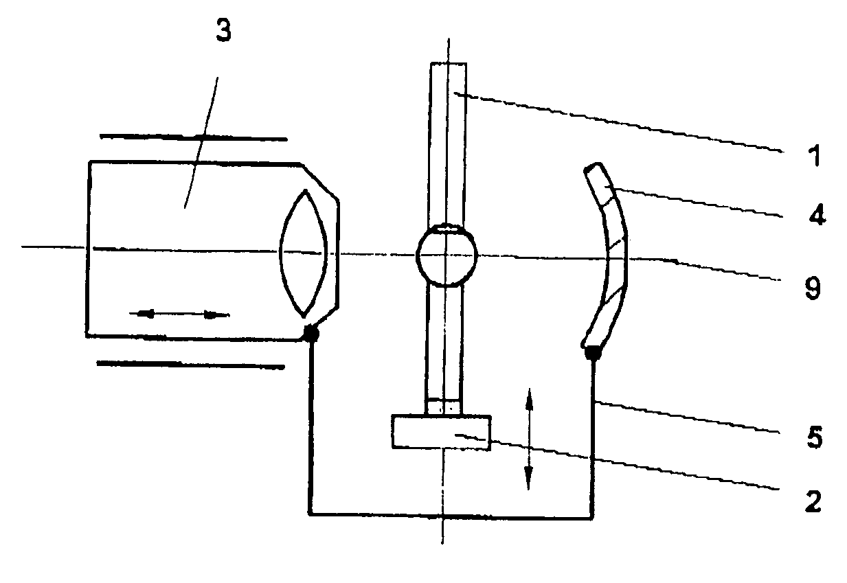
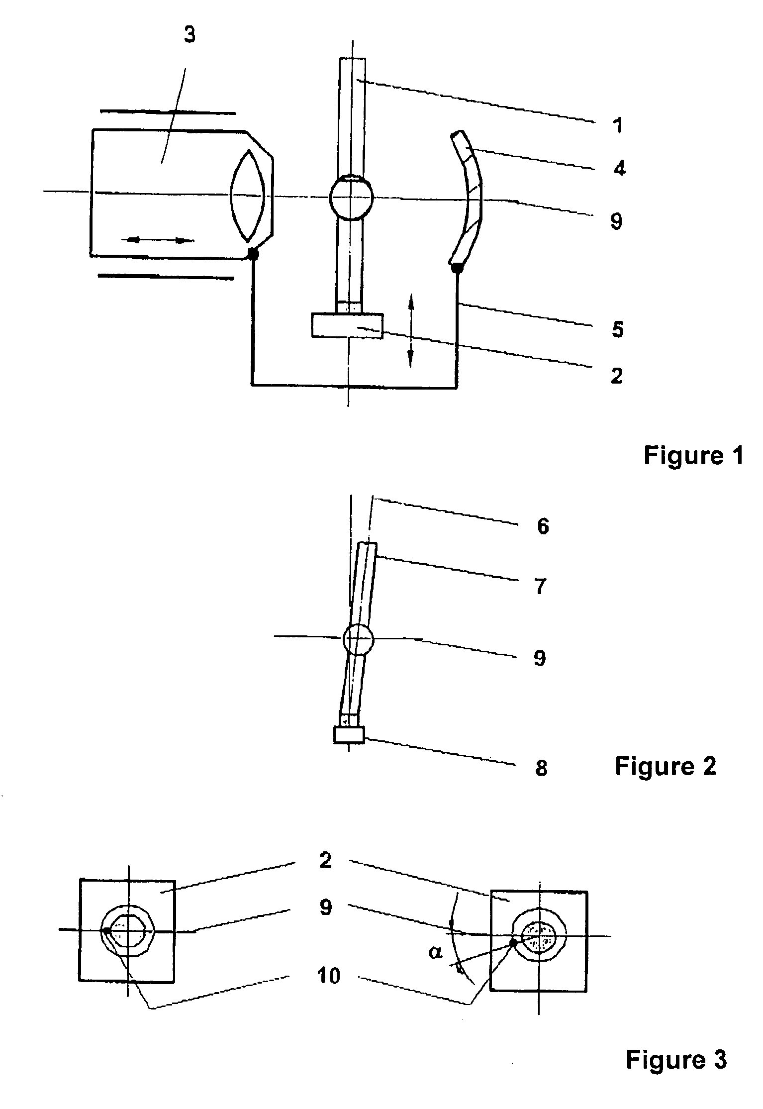
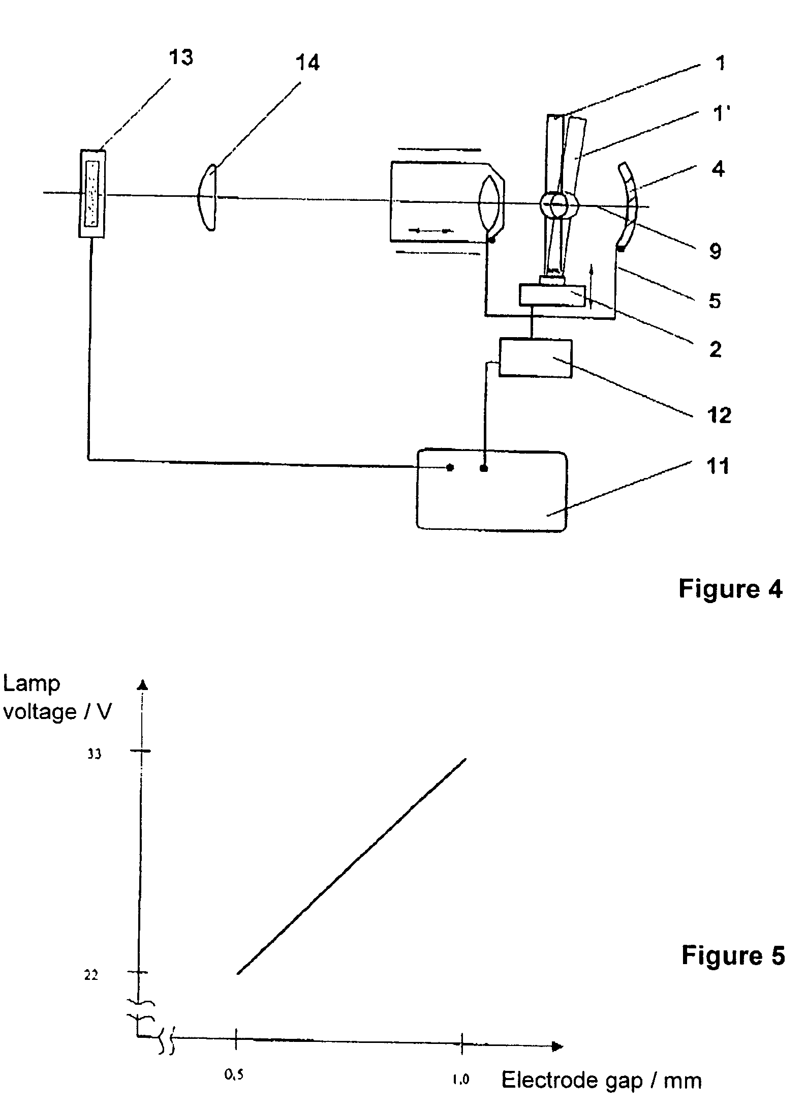
[0025]In the method and the apparatus, according to the invention, for the adjustment and automatic readjustment of the lamp in a microscope, the apparatus according to FIG. 1 comprises a lamp cap 2 which receives the lamp 1 and which is arranged between a collector 3 and a reflector 4 which form a mechanical unit 5. The collector-reflector unit 5 and the lamp cap 2 have devices for adjustment. The optical axis 9 of the collector 2 coincides with that of the reflector 4.

[0026]According to the method, the tilting direction 6 of the glass body 7 is determined relative to the lamp foot 8 and is marked at the lamp 1, preferably at the lamp foot 8. FIG. 2 shows a lamp 1 having an axial run-out. For oriented insertion of the marked lamp 1, the lamp cap 2 likewise has a mark 10 so that the tilting direction 6 of the lamp 1 lies in direction of the optical axis 9 of the collector 3 after insertion. FIG. 3 shows two marked lamp mounts.

[0027]In order to adjust, the collector-reflector unit 5 ...


PUM


Abstract

Method and apparatus for the adjustment and automatic readjustment of the lamp in a microscope. The present invention is used for adjusting the lamp in a microscope. In the solution according to the invention, the tilting direction of the glass body relative to the lamp cap is marked at the lamp. The lamp cap is likewise marked for oriented insertion of the marked lamp so that the tilting direction of the lamp lies in direction of the optical axis of the collector after insertion. For adjusting, the collector-reflector unit is displaced in direction of the optical axis of the collector and the lamp cap is then oriented in vertical direction of the optical axis of the collector. For automatic readjustment, the lamp cap has an actuating drive. A reference variable is determined for the actuating drive by a control unit by evaluating lamp voltage or lamp current. The proposed solution can be applied in all devices in which an ultra-high pressure gas discharge lamp is to be moved into and / or maintained in a focus position.

Description

CROSS-REFERENCE TO RELATED APPLICATION[0001]This application claims priority of German Application No. 103 45 367.9, filed Sep. 26, 2003, the complete disclosure of which is hereby incorporated by reference.BACKGROUND OF THE INVENTION[0002]a) Field of the Invention[0003]The present invention is directed to an apparatus and associated method for the adjustment of the lamp in a microscope. The lamp is to be brought into the focal plane and oriented therein corresponding to the optical axis.[0004]b) Description of the Related Art[0005]In fluorescence microscopy and light microscopy, ultra-high pressure gas discharge lamps, for example, ultra-high pressure xenon or mercury gas discharge lamps, are used as excitation light sources and illumination light sources and are to be positioned in the beam path in a corresponding manner. In order to make better use of the light flux radiated by the lamp, there is an additional reflector mirror which projects the image of the light arc as exactly ...

Claims


Application Information

Patent Timeline
Patent Type & Authority Patents(United States)
IPC IPC(8): G05B5/00H02H7/08H02P1/04H02P3/00H02P7/00G02B21/06
CPCG02B21/06
Inventor GONSCHOR, MATTHIAS
Owner CARL ZEISS MICROSCOPY GMBH
Why Eureka
Try Eureka