
Ionization devices

Inactive Publication Date: 2006-05-16
ION SCI
View PDF9 Cites 21 Cited by
  • Summary
  • Abstract
  • Description
  • Claims
  • Application Information

AI Technical Summary

Benefits of technology

[0012]The present invention therefore tackles the problem in a quite different way. Instead of attempting to prevent moisture reaching the sensor's ionisation chamber it seeks to prevent the inevitable spurious wall- or support-carried electrode current from being confused with the real, ion-derived current. And to achieve this result, the present invention provides an additional electrode at or nearly at the potential of the sensing electrode, which acts as a fence to “block” any current tracking along the walls or electrode supports. Typically this third (fence) electrode is placed within the ionisation chamber and physically located in or on the surrounds thereof between the counter electrode and the sensing electrode. This fence electrode does not affect—and is not affected by—the degree of condensation which may occur within the chamber, but provides a dramatically-extended integrity of measurement of gaseous ionisation under conditions of condensation or deposition of other electrolytically-conductive films within the chamber or on the electrode supports.

Problems solved by technology

Unfortunately, because the temperature of sampled gas varies as the detector is conveyed from place to place, the gas drawn into the monitor may on occasion experience a sufficient drop in temperature to cause dew or mist to form in the sampled gas drawn into the probe.
This mist may then condense on the probe walls, and even on or within the gas sensor itself, resulting in false readings, and even in damage to or failure of the sampler.
And again, any formed mist may condense within the device, and on or within the sensor itself, resulting in false readings, and possibly damage to or failure of the monitor.
Unfortunately, any contamination, such as condensation, on the surrounds of the chamber or the electrode supports and extending between the electrodes will provide an alternative route for electric current to flow between the electrodes, and if this happens then an increased but spurious signal is obtained from them which can obscure the small ion-derived current signal.
Although of course the problem of condensation can be tackled by using filters and water-absorbent materials in an attempt to remove any water vapour from the sampled air, this is often simply not practicable.
In addition, such filters and agents frequently remove the sought-after analytes themselves from the gas sample before they ever reach the gas sample chamber.

Method used


Image

  • Ionization devices
  • Ionization devices
  • Ionization devices

Examples


Embodiment Construction

[0068]It should be understood that these embodiments are only examples of the many advantageous uses of the innovative teachings herein. In general, statements made in the specification of the present application do not necessarily limit any of the various claimed inventions. Moreover, some statements may apply to some inventive features but not to others. In general, unless otherwise indicated, singular elements may be in the plural and vice versa with no loss of generality.

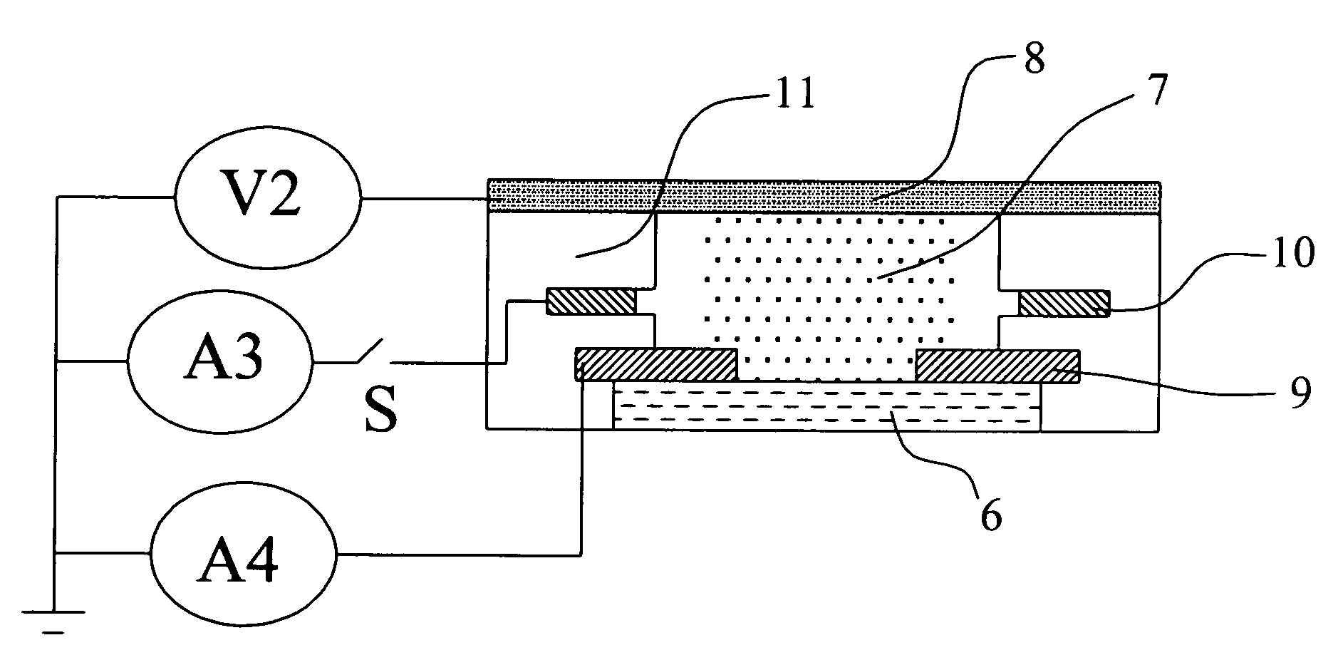
[0069]In FIG. 1 a photoionisation detector gas sampling chamber is depicted, where high energy light (from a source not shown) is caused to pass through a window of transmitting material (6). Ions are generated in the sample chamber gaseous space (approximately depicted by the area (7)). Positively-charged ions are picked up by the counter electrode (8) whilst negative ions are picked up by the sensing electrode (9). Between these electrodes is located the fence electrode (10), supported by electrically insulati...


PUM


Abstract

An ionization detector includes a third (fence) electrode (55) between the counter electrode (53) and the sensing electrode (54). The fence electrode (53) is maintained at or near the potential of the sensing electrode (54) and traps charge movement (electrolytic current) along the detector walls associated with condensation and / or contamination within the detector. In a photoionisation detector, the fence electrode is also adapted to trap photo-induced current originating from the cathode (53).Current drawn from the fence electrode (53) provides a measure of the degree of contamination or condensation within the detector and of lamp efficiency.

Description

CROSS-REFERENCE TO RELATED APPLICATIONS[0001]This application is based upon and claims priority from PCT / GBO2 / 05236, filed on Nov. 20, 2002, which is based on and claims priority from British Application 0206769.2 filed on Mar. 22, 2002, and claims priority from British Application 0127705.2 filed on Nov. 20, 2001, the entire disclosure of each of the aforementioned applications are each herein incorporated by reference in their entirety.FIELD OF THE INVENTION[0002]This present invention generally relates to with gas or vapour detectors and methods of operating them, and more particularly relates to devices that involve the detection of ions passing through or across a high-impedance medium (such as air or a ceramic surface). It is especially concerned with such devices that are intended for sampling gases, such as air, for specific additional gaseous constituents.BACKGROUND OF THE INVENTION[0003]It is frequently desirable to ascertain whether the air in or around a locality such as...

Claims


Application Information

Patent Timeline
IPC IPC(8): G01N27/62
CPCG01N27/62
Inventor DEAN, WILLIAM FRANCIS HOULTONSTOCKDALE, MARK JULIAN
Owner ION SCI
Learn More