Power supply device comprising several switched-mode power supply units that are connected in parallel

a power supply device and power supply unit technology, applied in the direction of power conversion systems, dc-dc conversion, dc source parallel operation, etc., can solve the problems of reducing the complexity of the circuitry, and the higher cost incurred, so as to reduce the overall efficiency of the power supply and the system

Inactive Publication Date: 2006-05-16
MINEBEA CO LTD
View PDF10 Cites 30 Cited by
  • Summary
  • Abstract
  • Description
  • Claims
  • Application Information

AI Technical Summary

Benefits of technology

[0016]The power supply device according to the invention makes it possible to adjust the output characteristic of a switch-mode power supply according to specifications in several different operating ranges, the adjustment being largely loss-free due to the use of the P element, the current imaging circuit and the amplifier circuit, but nevertheless requiring a less complex circuitry than is the case with an active current division which is based on measuring the output currents of all the switch-mode power supplies and effecting control depending on the measurement of all the switch-mode power supplies.
[0024]An advantage of using a P element according to the invention is that current-dependent characteristics can be generated, in contrast to segment 1 of DE 100 19 329, and that the equations of the straight lines can be set more easily. This is important for the load division when several power supplies are operated in parallel.

Problems solved by technology

The disadvantages can be seen in the greater complexity of the circuitry and the higher costs thus incurred.
A disadvantage is the somewhat less exact division of current in some applications.
Although the above-described prior art solution for establishing the output characteristic of the switch-mode power supplies as a function of the output current has a simple circuitry and allows for different operating ranges of the output characteristic, the shunt resistors, which can be located in the power supply unit or outside it in the output line of the switch-mode power supply (s.RL in FIG. 2), generate considerable losses and thus reduce the overall efficiency of the power supply and of the system.

Method used


Image

  • Power supply device comprising several switched-mode power supply units that are connected in parallel
  • Power supply device comprising several switched-mode power supply units that are connected in parallel
  • Power supply device comprising several switched-mode power supply units that are connected in parallel

Examples


Embodiment Construction

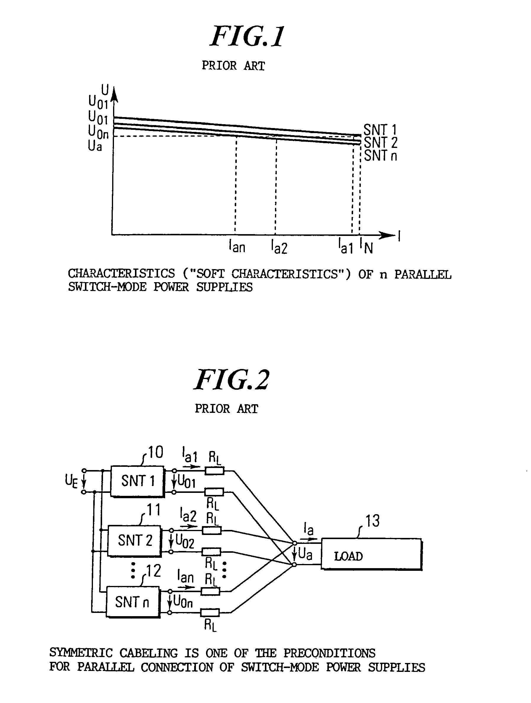
[0034]FIG. 1, which has been described above, shows a diagram with three so-called “soft” characteristics of three switch-mode power supplies connected in parallel with a passive current division according to the prior art. An example of three or n switch-mode power supplies connected in parallel according to the prior art is shown in FIG. 2. FIG. 2 shows a first switch-mode power supply 10, a second switch-mode power supply 11, and an nth switch-mode power supply 12, which are connected in parallel and wired symmetrically to a load 13. The line resistances of the wiring are schematically represented by the resistors RL. In the arrangement shown in FIG. 2, the line resistors RL correspond to the first shunt resistor to set the output characteristic of each switch-mode power supply 10, 11, 12, it being necessary in the prior art to provide an additional shunt resistor in order to achieve an exact current division. This solution is inflexible, however, and results in additional losses...


PUM


Abstract

The invention relates to a power supply device having several switch-mode power supplies connected in parallel to supply at least one consuming unit, each switch-mode power supply generating an output current I0 and an output voltage U0(I0, RL) that is a function of the output current I0 and a load resistance RL, and having a control device for each switch-mode power supply, the control device having a first stage with a P element (54) that receives a P element input voltage which is derived from the output voltage U0(I0, RL), and generates a P element control voltage UVS, that is used to control the respective switch-mode power supply, the first stage being active when 0≦I0≦I0P, a second stage having a current reproduction circuit which reproduces the output current I0 of the respective switch-mode power supply and generates an output current control voltage UP which is used to control the respective switch-mode power supply, the second stage being active when I0P≦I0≦I0S, and a third stage having an amplifier circuit which amplifies a signal proportional to the output current I0 and generates an amplified output current control voltage m·US which is used to control the respective switch-mode power supply, the third stage being active when I0S≦I0≦IK.

Description

CROSS REFERENCE TO RELATED APPLICATIONS[0001]This application is a National Stage of International Application No. PCT / EP03 / 03275, filed Mar. 28, 2003, which claims priority to German patent application 102 14 190.8, filed Mar. 28, 2002, the entire contents of each of which are hereby incorporated by reference.FIELD OF THE INVENTION[0002]The invention relates to a power supply device having several switch-mode power supplies connected in parallel to supply at least one load, each switch-mode power supply generating an output current and an output voltage, and having a control device for each switch-mode power supply. The control device controls the output voltage of the switch-mode power supply which is a dependent on the output current and a load resistance.BACKGROUND OF THE INVENTION[0003]The basic principles of switch-mode power supplies connected in parallel are described, for example, in Elektronik, Volume 13, 2000, pages 114–118 “Schaltnetzteile parallel geschaltet-technische ...

Claims


Application Information

Patent Timeline
Patent Type & Authority Patents(United States)
IPC IPC(8): H02M3/335H02M3/158H02M3/28
CPCH02M3/1584
Inventor HOFFMAN, HANSRATHMANN, ROBERTWIESMUELLER, DAVID
Owner MINEBEA CO LTD
Why Eureka
Try Eureka