
Method of and arrangement for minimizing power consumption and data latency of an electro-optical reader in a wireless network

Active Publication Date: 2006-05-16
SYMBOL TECH LLC
View PDF9 Cites 35 Cited by
  • Summary
  • Abstract
  • Description
  • Claims
  • Application Information

AI Technical Summary

Benefits of technology

[0010]Accordingly, it is an object of this invention to minimize power consumption and to minimize data latency of a battery-operated, wireless reader.
[0011]Another object is to increase the working lifetime of a battery used to power handheld, electro-optical readers.

Problems solved by technology

As advantageous as the use of batteries are, experience has shown that they are unsatisfactory in certain applications.
The reader has electrical components which consume power and, over the course of a day, for example, a six-hour shift, the battery weakens and discharges.
The battery could be recharged, but this requires down-time during which the reader is unusable.
A spare battery could be used as a replacement, but this represents still another accessory to be carried and possibly misplaced.
A larger battery would not discharge as quickly as a smaller one, but the larger battery adds extra weight and, again, is not a satisfactory answer to the delivery person who wishes to lighten his or her load, particularly if the reader is a wearable device such as a finger-mounted reader.
The use of wireless transceivers has also proven unsatisfactory in certain cases.

Method used


Image

  • Method of and arrangement for minimizing power consumption and data latency of an electro-optical reader in a wireless network
  • Method of and arrangement for minimizing power consumption and data latency of an electro-optical reader in a wireless network
  • Method of and arrangement for minimizing power consumption and data latency of an electro-optical reader in a wireless network

Examples


first embodiment

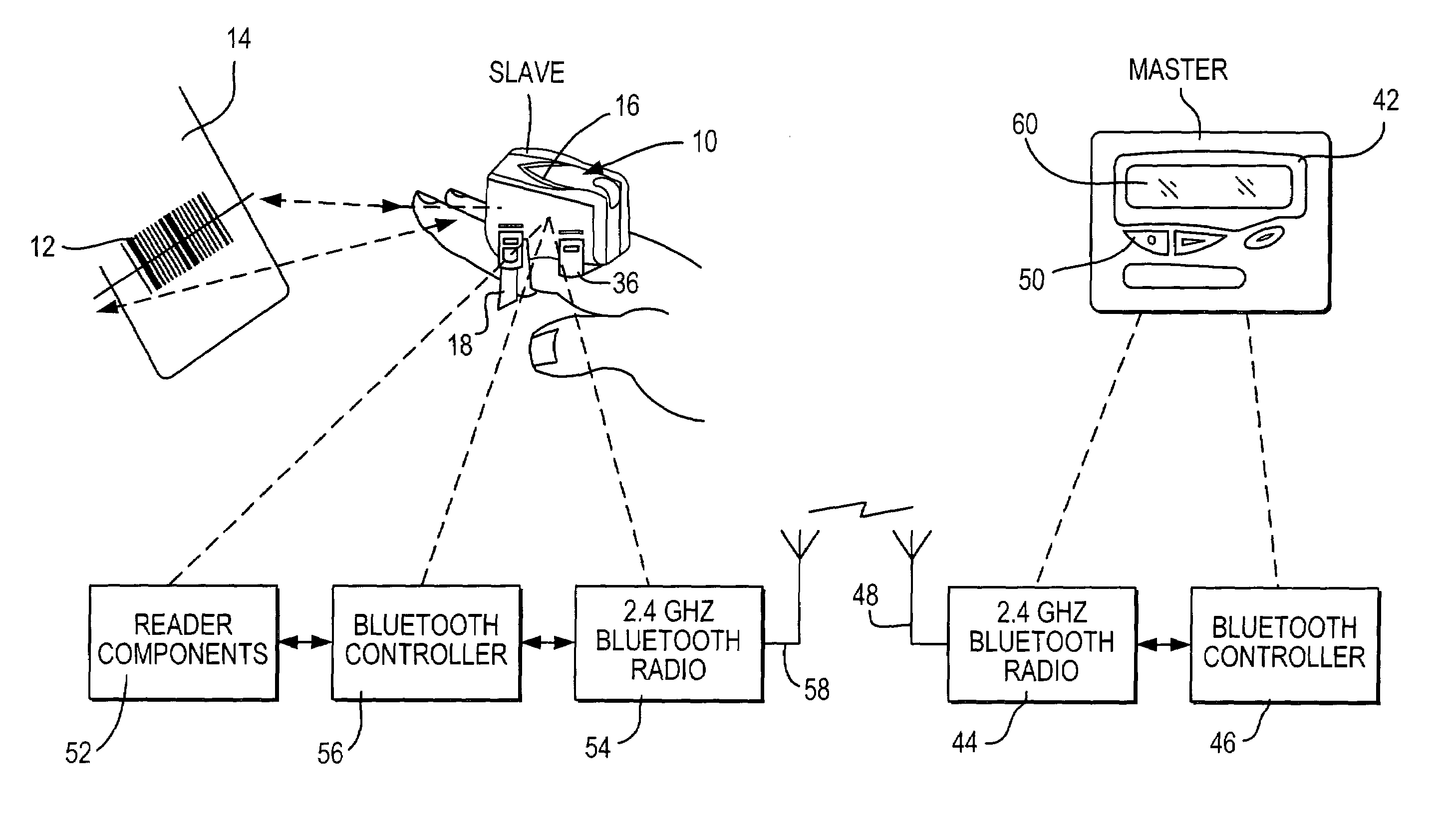
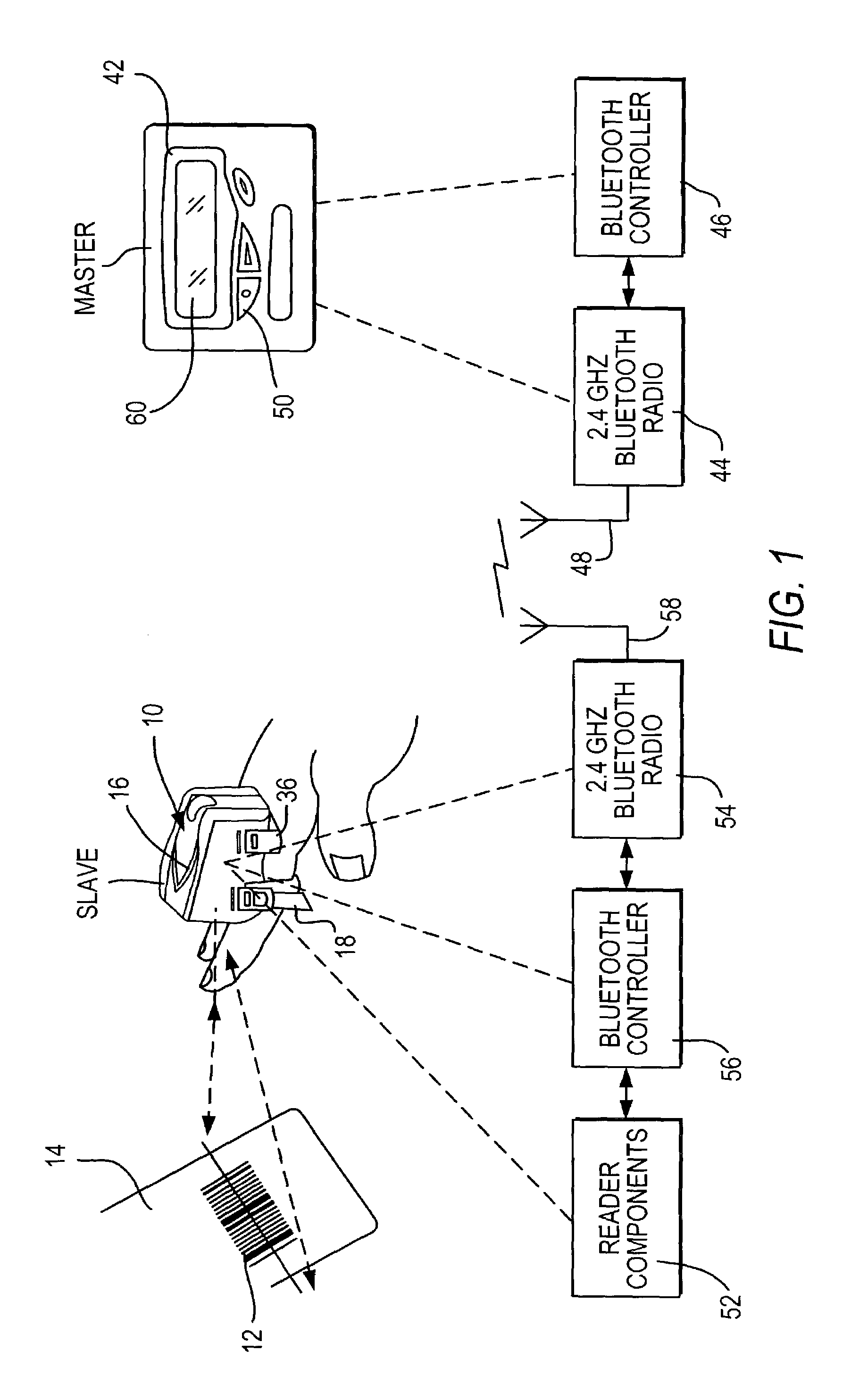
[0036]In accordance with this first embodiment of the invention, a new operational mode that allows both low power and low data latency is activated in the slave radio 54 of the reader by using a vendor-specific, custom, host control interface (HCI) command. The slave controller 56 sends the HCI command in packet form to the slave radio 54. The HCI command contains two parameters to specify the duty cycle, namely the “wake time” during which the slave is actively listening for signals from the master, and the “sleep time” during which the slave is not listening for signals from the master.

[0037]In this new mode, the master operates normally by continuously trying to communicate with the slave. However, if the reader has no data to send to the master, that is, the reader has not read a symbol, then the slave will respond at fixed time intervals or the wake times specified by the HCI command. In fact, the slave will not even attempt to listen for signals from the master during the sle...

second embodiment

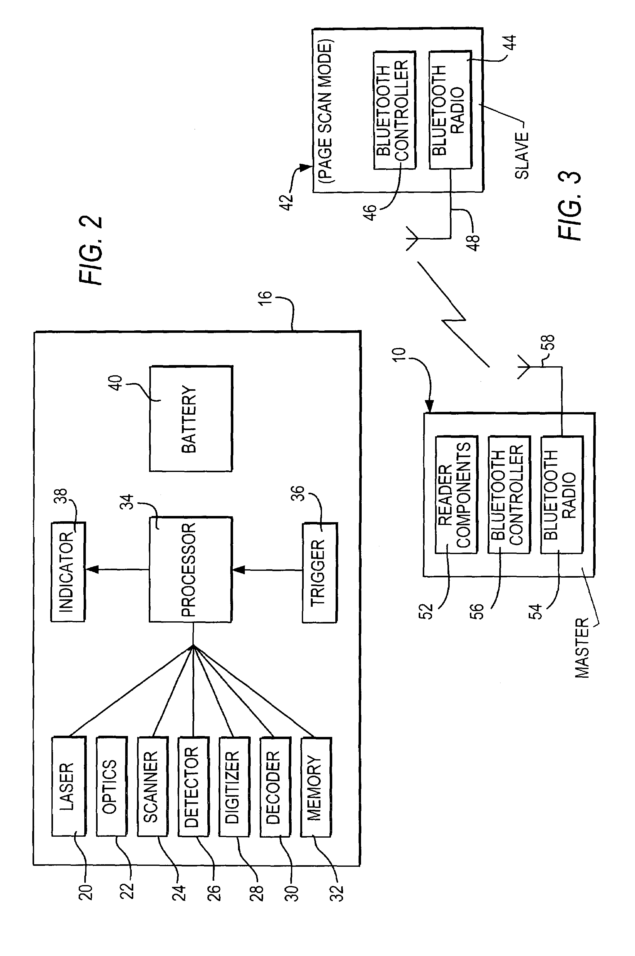
[0043]In this second embodiment, the radio 54 in the reader would normally be off. When the reader has data to send to the terminal, such as from a scanned symbol, the controller 56 would turn the radio 54 on and attempt to page the terminal. The page function is used to establish a piconet with a Bluetooth device that is in page scan mode. Since the terminal is always in the page scan mode, the connection will be established quickly. This can be assured by having the reader quickly scan through all possible frequencies that the terminal could be listening to. Since the reader initiated the connection, it operates as the master, and the terminal operates as the slave in the resulting piconet shown in FIG. 3. Once the piconet is established, the reader sends the data to the terminal and then immediately terminates the piconet. The reader then turns the radio 54 off and waits until the reader has more data to send.

[0044]This second embodiment requires no radio activity by the reader w...


PUM


Abstract

Battery power consumption and data transfer latency of an electro-optical reader in a wireless network are minimized by turning a radio off in a default state, and by turning the radio on only after the reader has generated data to be transferred along the network.

Description

CROSS REFERENCE TO RELATED APPLICATIONS[0001]This application claims the priority benefit of U.S. provisional patent application Ser. No. 60 / 345,289, filed Oct. 25, 2001.BACKGROUND OF THE INVENTION[0002]1. Field of the Invention[0003]This invention relates to a method of and an arrangement for minimizing power consumption of a battery-operated, wireless reader for electro-optically reading machine-readable indicia such as bar code symbols, and of minimizing latency of data generated by, and transferred from, the reader to a wireless data collection terminal remote from the reader and in wireless communication therewith over a short range network, especially a Bluetooth network in which the reader and the terminal are Bluetooth-compatible devices in compliance with Bluetooth standard, version 1.1.[0004]2. Description of the Prior Art[0005]A reader for electro-optically reading machine-readable indicia such as bar code symbols, both one- and two-dimensional, is well known in the art. ...

Claims


Application Information

Patent Timeline
IPC IPC(8): H04B1/38H04B1/16
CPCH04W52/0229Y02B60/50Y02D30/70
Inventor SACKETT, WILLIAMLEVINE, ADAMCONNOLLY, SEANBIUSO, ANTHONYSHELLHAMMER, STEPHENBOCCUZZI, FRANKCORDES, KEVIN
Owner SYMBOL TECH LLC
Learn More