
Machinery for improving performance irregularities arising from vibrations

a technology of vibration and damping mechanism, applied in the field of machinery, can solve the problems of vibration more easily occurring with speed and precision increases, performance irregularities, high speed and high precision, etc., and achieve the effect of improving performance irregularities arising from vibrations

Inactive Publication Date: 2006-05-16
MITUTOYO CORP
View PDF4 Cites 27 Cited by
  • Summary
  • Abstract
  • Description
  • Claims
  • Application Information

AI Technical Summary

Benefits of technology

[0010]The present invention was conceived in light of the above problem of the prior art, and the object thereof is to provide a machinery that can improve performance irregularities arising from vibrations.
[0016]The controller allows the actuator to generate the vibration having a negative phase relationship with respect to the inherent vibration detected by the sensor.
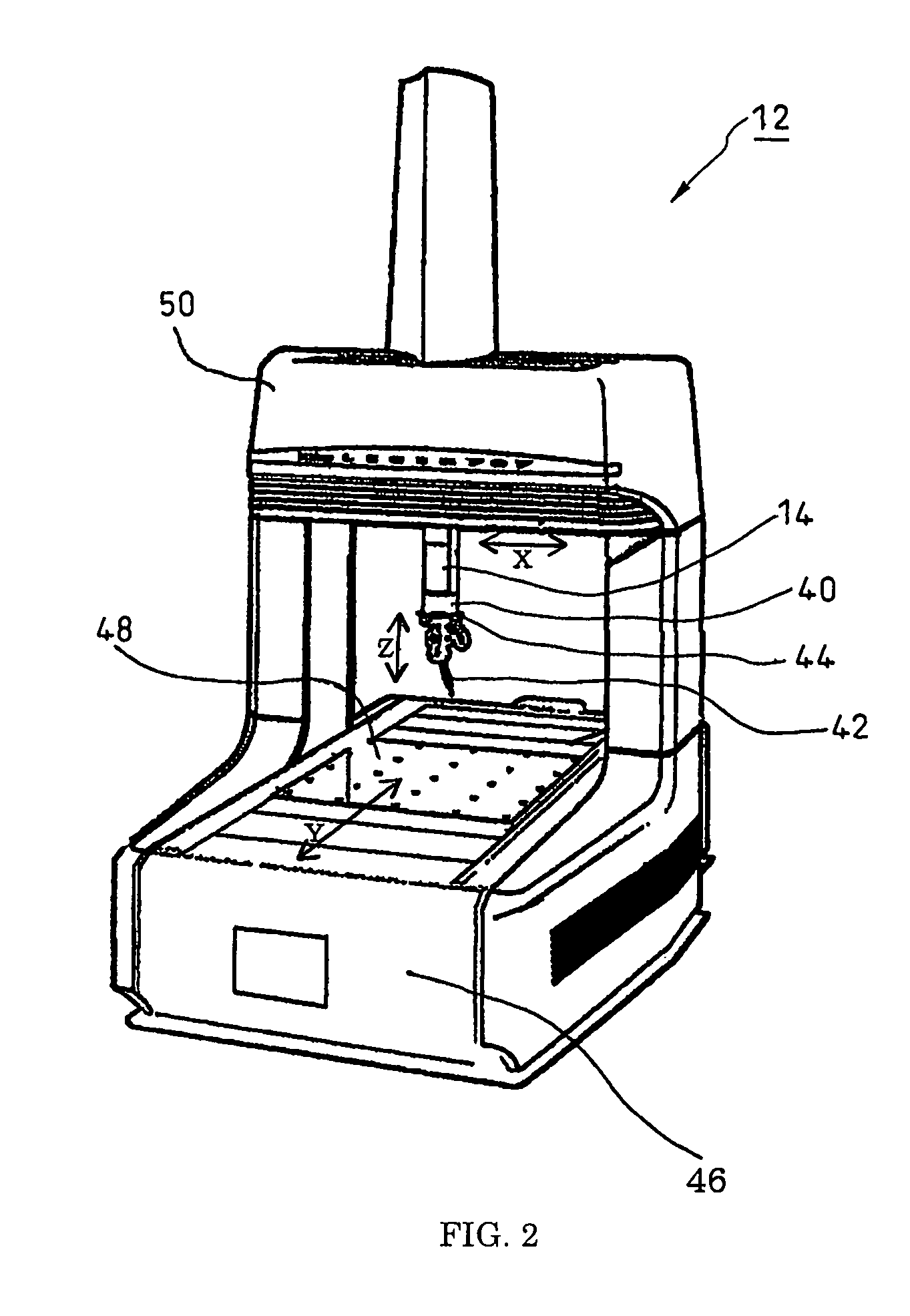
[0031]The coordinate measuring machine of the present invention is called a three-dimensional coordinate measuring machine. The three-dimensional coordinate measuring machine is provided with mutually perpendicular guides, and a scale and the probe that obtain the movement amount of the guides. The coordinate measuring machine can thereby obtain three-dimensional coordinate values for the probe based on the obtained movement amount.

Problems solved by technology

Although these types of precision instruments require high speed and high precision, vibrations more easily occur with increases in speed and precision.
In the precision instruments, there are the performance irregularities arising from the vibrations occurred by the instruments.
However, even if the elastic rubber, etc., or the prior art methods described in the aforementioned patent documents are used to increase the speed and precision of precision instruments, a satisfactory damping effect cannot be attained.
In seeking to further increase the speed and precision of precision instruments, there is a limit to the increase the speed and precision because more vibrations are occurred.
In precision instruments, although there is still room for improvement in performance irregularities due to vibrations, there has been no suitable technology that can solve this problem in the prior art.

Method used


Image

  • Machinery for improving performance irregularities arising from vibrations
  • Machinery for improving performance irregularities arising from vibrations
  • Machinery for improving performance irregularities arising from vibrations

Examples


Embodiment Construction

[0039]The preferred embodiment of the present invention will be described hereunder with reference to the drawings.

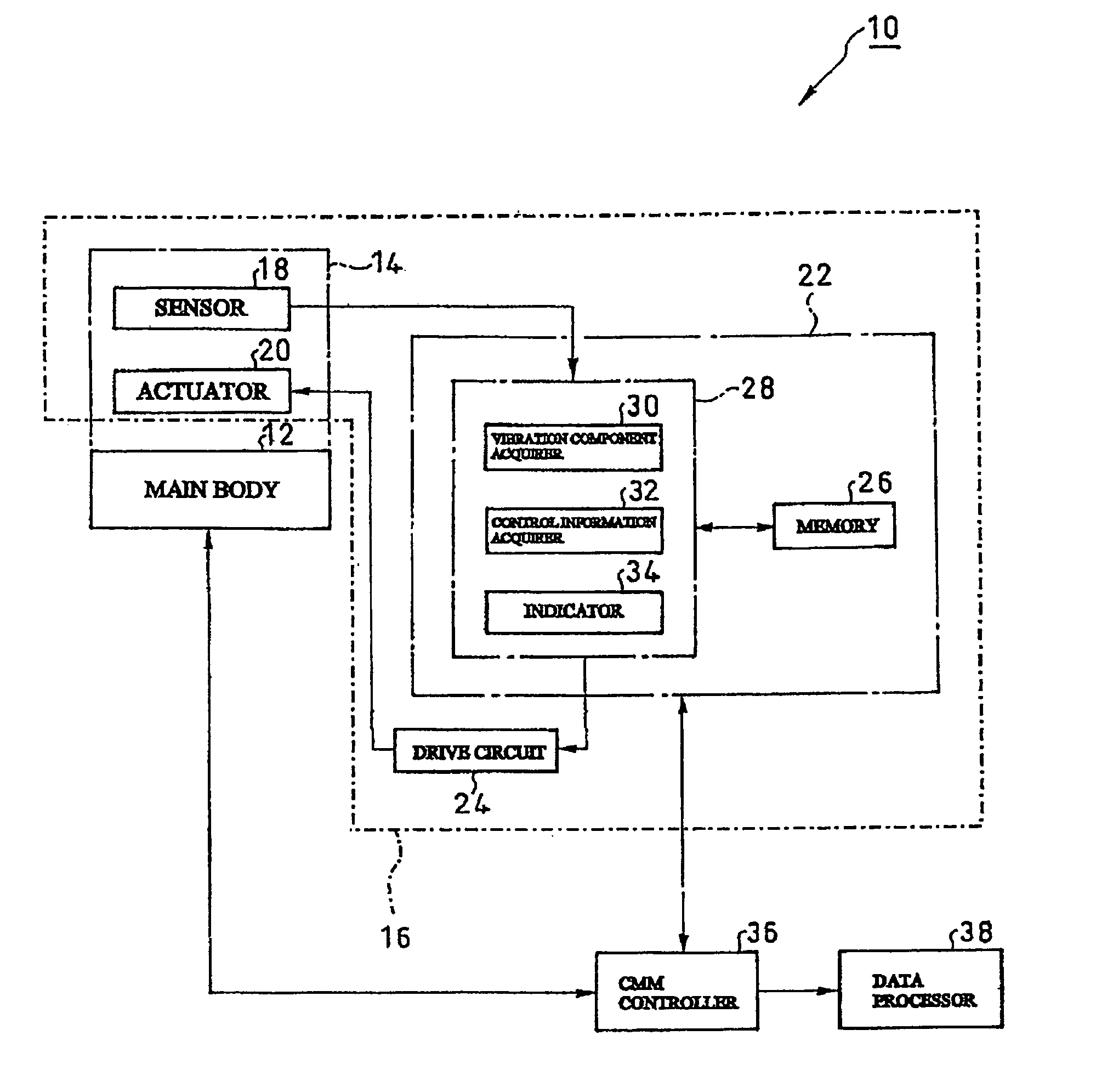
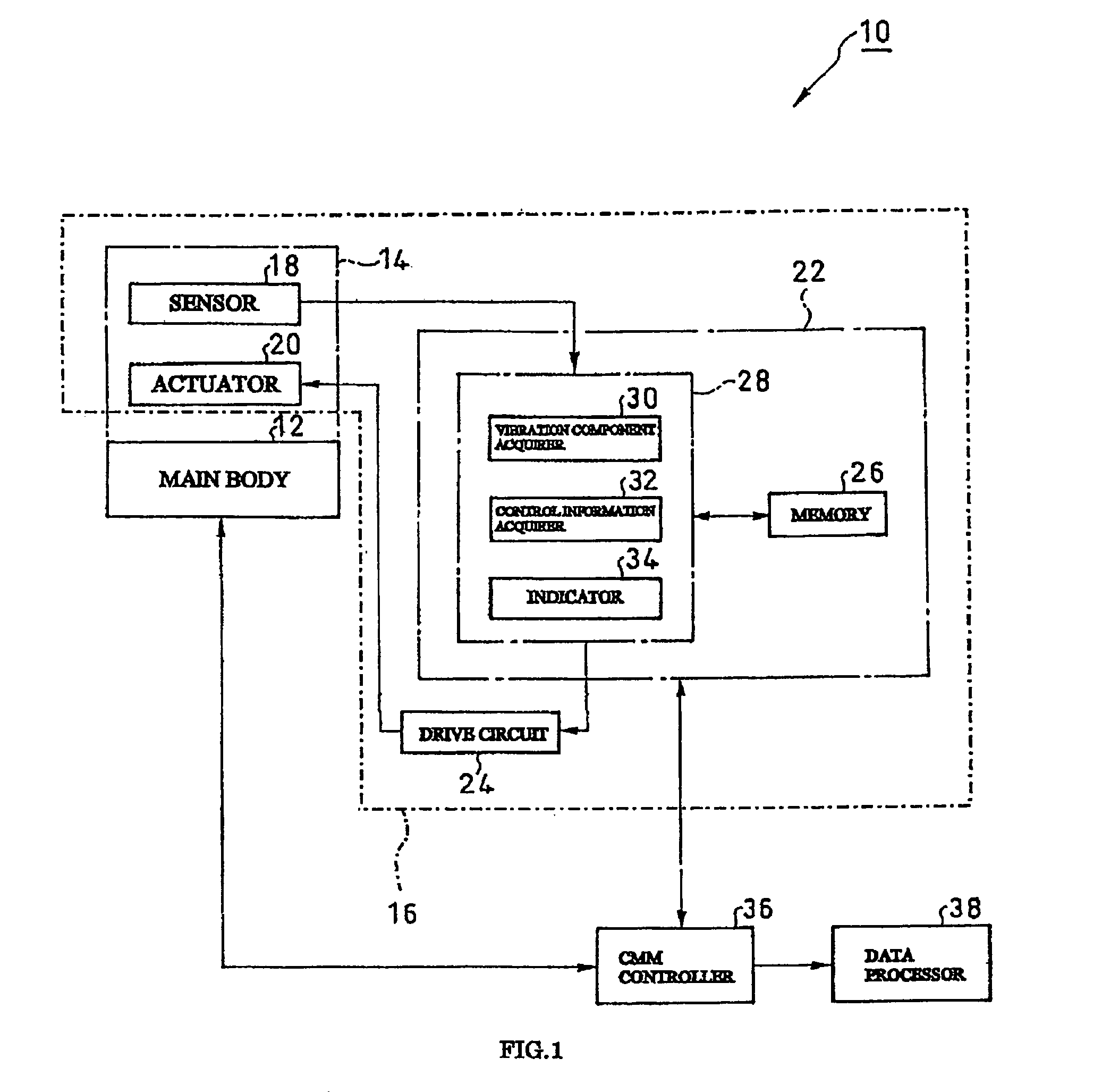
[0040]FIG. 1 shows a schematic structure of a machinery according to an embodiment of the present invention.

[0041]In the present embodiment, as a movable body that is to be damped, a Z axis spindle that moves in an X axis direction in a state where it is provided with a probe of a coordinate measuring machine will be assumed. An example wherein damping of the inherent vibration in the X axis direction of the probe is performed will be explained.

[0042]The coordinate measuring machine (machinery) 10 shown in the drawing is provided with coordinate measuring machine main body (main body) 12, a Z axis spindle (movable body) 14, and an active damper 16.

[0043]Here, the Z axis spindle 14 moves linearly in an X axis direction (direction of movement) with respect to the coordinate measuring machine main body 12.

[0044]The active damper 16 is provided with a sensor 18, an actuator...


PUM


Abstract

A machinery is disclosed that comprises a movable body that moves linearly with respect to a main body and an active damper for controlling an inherent vibration of the movable body occurred in a direction of movement of the movable body, the active damper comprising a sensor, provided with the movable body, for detecting the inherent vibration currently occurred in the direction of movement of the movable body, among one or a plurality of the inherent vibrations of the movable body; an actuator, provided with the movable body, for generating a vibration in the direction of movement of the movable body; and a controller for allowing the actuator to generate the vibration having a negative phase relationship with respect to the inherent vibration detected by the sensor.

Description

RELATED APPLICATIONS[0001]This application claims priority to the Japanese Patent Application 2003-134434 dated on May 13, 2003 and is hereby incorporated with reference for all purposes.BACKGROUND OF THE INVENTION[0002]1. Field of the Invention[0003]The present invention relates generally to machinery, and more particularly, to improvement of a damping mechanism of the machinery.[0004]2. Prior Art[0005]Precision instruments such as coordinate measuring machine are provided with movable bodies. Although these types of precision instruments require high speed and high precision, vibrations more easily occur with increases in speed and precision. Precision instruments in particular require improvements in relation to performance irregularities. In the precision instruments, there are the performance irregularities arising from the vibrations occurred by the instruments. If these vibrations can be suppressed, the speed and precision of the precision instruments can be further increased...

Claims


Application Information

Patent Timeline
IPC IPC(8): G05B13/00G01B21/00F16F15/00F16F15/02G01H11/00G01M1/00G05B19/404G05D19/02G05D23/00
CPCF16F15/223G05B19/404G05B2219/49054G05B2219/49048
Inventor OGURA, KATSUYUKIANZAI, HIROTADA
Owner MITUTOYO CORP
Learn More