Magnetic sensor with limited element width

a magnetic sensor and element width technology, applied in the field of noncontact magnetic sensors, can solve the problems of increasing the size the power consumption of the magnetic switch, and the inability to provide stable operation, so as to achieve stable operation and easily control the magnetic sensitivity

Inactive Publication Date: 2008-02-07
ALPS ALPINE CO LTD
View PDF5 Cites 13 Cited by
  • Summary
  • Abstract
  • Description
  • Claims
  • Application Information

AI Technical Summary

Benefits of technology

[0022] The magnetic sensor provided with the magneto-resistance element having the hysteresis characteristic as just described may have a control unit outputting a switching signal on the basis of an output variation due to a variation in a magnitude of the external magnetic field. Therefore, an ON and OFF switching signal may be outputted on the basis of the variation of the magnitude of the external magnetic field. For example, if the magnetic sensor according to the application is close to the magnet, then an ON signal (or OFF signal) is outputted, and if the magnet withdraws from the magnetic sensor, then an OFF signal (or ON signal) is outputted. For example, the magnetic sensor according to the application may be effectively used in an opening and closing detection of the foldable cellular phone.
[0023] In the above-mentioned configuration, a magnetic sensor may prevent an occurrence of a chattering or the like to obtain a stable operation. Additionally, a magnetic sensor may easily control a magnetic sensitivity depending on applications.

Problems solved by technology

However, the magnetic switch using the Hall element disclosed in Patent Document 1 could not have provided a stable operation, since such an erroneous operation occurs when external noises and the like get mixed in the switch.
If the method setting the larger current I is applied, a power consumption of the magnetic switch increases.
Therefore, the magnetic switch increases in size in the former method and a cost rises in the later method.
Larger element widths, larger than 5 μm, cause a decrease in the coercive force and lead to a malfunction such as an unexpected chattering and, in addition, cause a decrease in the resistance of the magneto-resistance element.
From the result, a decrease in size of the magnetic sensor may not be promoted.

Method used


Image

  • Magnetic sensor with limited element width
  • Magnetic sensor with limited element width
  • Magnetic sensor with limited element width

Examples


examples

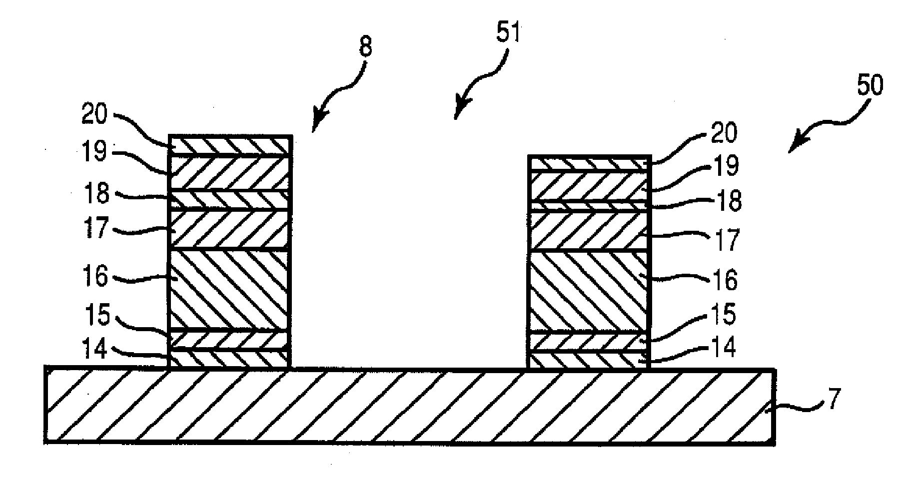
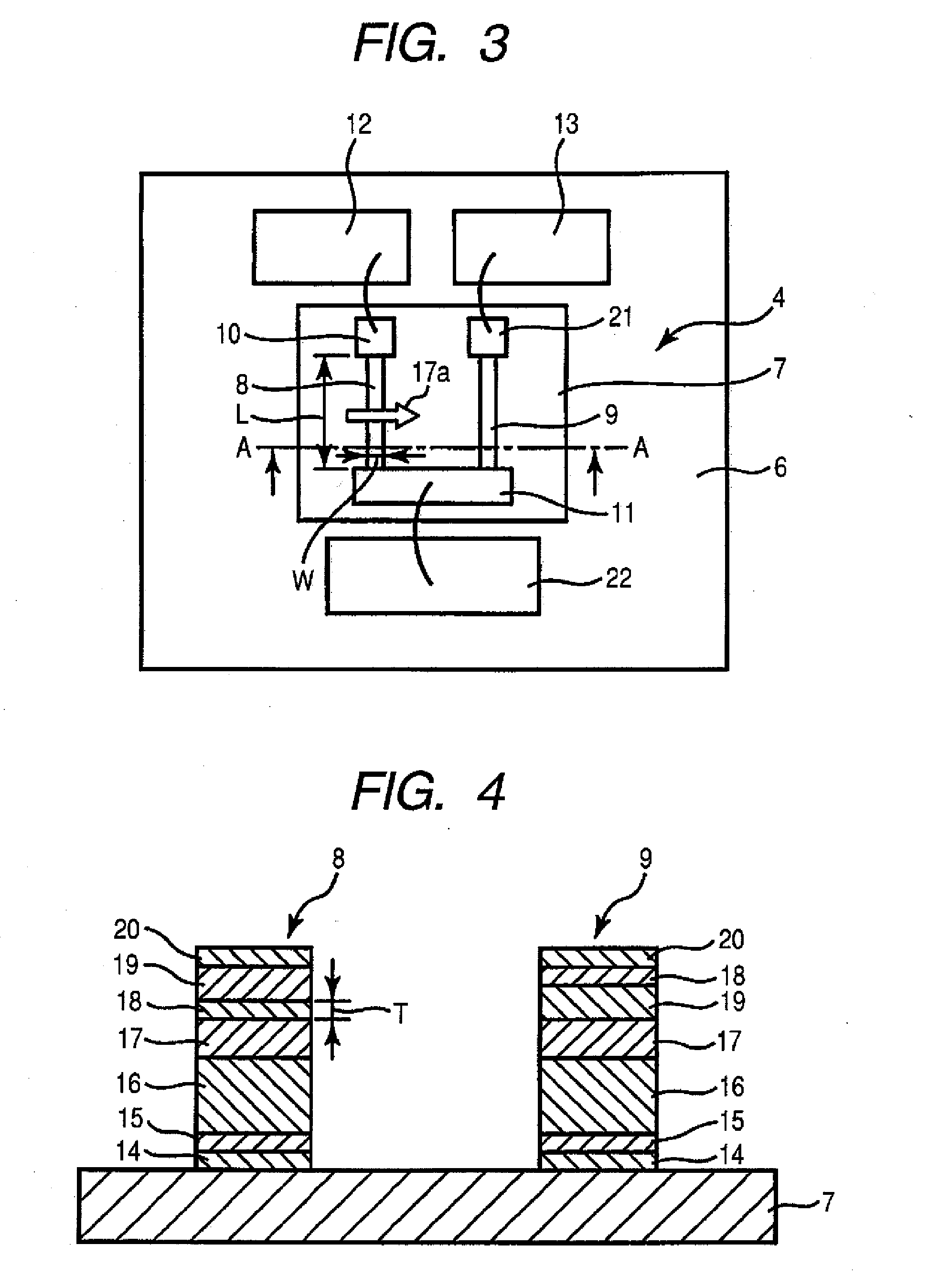
[0089] By using the magneto-resistance element 8 of a line shape illustrated in FIG. 3, a relation between the element width W and the coercive force Hc of the free layer 19 was researched.

[0090] A film configuration of the magneto-resistance element 8 using in the experiment was sequentially laminated from the bottom of a seed layer: NiFeCr / an anti-ferromagnetic layer: IrMn / a fixed layer: [FC30at % Co70at % / Ru / CoFe] / a non-magnetic layer: Cu / a free layer: [CoFe / NiFe] / a passivation layer: Ta. After forming films of the magneto-resistance element 8, a heat process under a magnetic field was performed to thereof so as to fix the magnetization direction of the fixed layer in one direction. The free layer was formed of CoFe having a thickness of 10 Å and NiFe having a thickness of 30 Å.

[0091] According to the experiment, a relation between the element width W at the time when the element length L of the magneto-resistance element 8 was changed in the range of 50 μm to 250 μm and the co...


PUM

PropertyMeasurementUnit
widthaaaaaaaaaa
lengthaaaaaaaaaa
coercive force Hcaaaaaaaaaa

Abstract

A magnetic sensor is provided. The magnetic sensor includes a magneto-resistance element. The magneto-resistance element includes an anti-ferromagnetic layer, a fixed magnetic layer being in contact with the anti-ferromagnetic layer, and a free magnetic layer. The free magnetic layer opposes the fixed magnetic layer via a non-magnetic layer interposed therebetween. The free magnetic layer has a magnetization direction that varies in accordance with an external magnetic field. The magneto-resistance element has a narrow and longitudinal shape and has an element length L greater than an element width W that is in the range of about 1 μm to 5 μm.

Description

[0001] This patent document claims the benefit of Japanese Patent Application No. 2006-094230 filed on Mar. 30, 2006, which is hereby incorporated by reference. BACKGROUND [0002] 1. Field [0003] The present embodiments relate to a non-contact magnetic sensor. [0004] 2. Related Art [0005] A non-contact switch such as a magnetic switch using a Hall element is known (for example, see Patent Document 1: Japanese Unexamined Patent Application Publication No. 8-17311). A magnetic switch using a magneto-resistance element is also known (for example, see Patent Document 2: Japanese Unexamined Patent Application Publication No. 2003-66127). [0006] However, the magnetic switch using the Hall element disclosed in Patent Document 1 could not have provided a stable operation, since such an erroneous operation occurs when external noises and the like get mixed in the switch. [0007] Additionally, it is well known that an output voltage V of the Hall element is determined by the formula of V=RH·I·B...

Claims


Application Information

Patent Timeline
Patent Type & Authority Applications(United States)
IPC IPC(8): G11B5/39G11B5/127
CPCB82Y25/00G01R33/07Y10T428/1121Y10T428/1143G01R33/093
Inventor SASAKI, YOSHITO
Owner ALPS ALPINE CO LTD
Why Eureka
Try Eureka