Method for automatically calibrating the frequency range of a PLL and associated PLL capable of automatic calibration

a technology of automatic calibration and frequency range, which is applied in the field of phase locked loops (plls), can solve the problems of adding to the cost of manufacturing the pll

Inactive Publication Date: 2006-05-16
AIROHA TECHNOLOGY CORPORATION
View PDF8 Cites 45 Cited by
  • Summary
  • Abstract
  • Description
  • Claims
  • Application Information

AI Technical Summary

Benefits of technology

[0013]It is therefore a primary objective of the claimed invention to provide a method for automatically calibrating the frequency range of a phase lock loop (PLL), to solve the above-mentioned problems.

Problems solved by technology

This factory testing and hard-wiring of the VCO adds to the cost of manufacturing the PLL.

Method used


Image

  • Method for automatically calibrating the frequency range of a PLL and associated PLL capable of automatic calibration
  • Method for automatically calibrating the frequency range of a PLL and associated PLL capable of automatic calibration
  • Method for automatically calibrating the frequency range of a PLL and associated PLL capable of automatic calibration

Examples


first embodiment

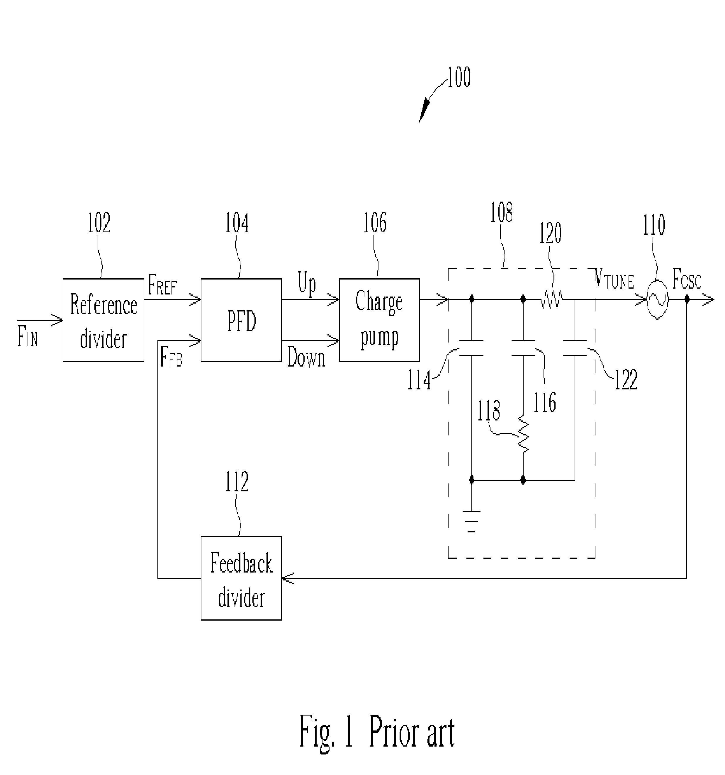
[0030]FIG. 3 shows a block diagram a PLL 300 capable of automatic calibration according to the present invention. The PLL 300 includes a reference divider 302, a phase / frequency detector (PFD) 304, a charge pump 306, a switch 308, a loop filter 310, a pre-charge unit 311, a voltage controlled oscillator 312, a feedback divider 314, a frequency detector 316, a VCO controller 318, and a loop controller 320. During normal PLL operations, the switch 308 connects the output of the charge pump 306 to the loop filter 310 and the operation of the reference divider 302, the PDF 304, the charge pump 306, the loop filter 310, the VCO 312, and the feedback divider 314 is the same as explained for FIG. 1. However, unlike the conventional PLL described in FIG. 1, when the PLL 300 is switched on, it uses a linear search to automatically calibrate the VCO frequency range, preventing the need to hardwire the frequency range during manufacturing, accounting for process variations, and allowing the PL...

second embodiment

[0046]In the present invention, when starting the automatic calibration process, the pre-charge unit 702 charges the loop filter to a middle voltage value and the VCO controller 708 sets the VCO to the middle frequency range and initializes an iteration counter j to 1. The frequency detector 706 compares the reference signal FREF with the feedback signal FFB. If the second rising edge of the reference signal FREF leads the second rising edge of feedback signal FFB, then the frequency detector 316 asserts “Shift Up” for the time duration between the two edges. When the VCO controller 318 receives the “Shift Up” signal, this means the feedback signal is too slow and the VCO controller 318 increases the VCO frequency range by (number of ranges) / 2j+1, where j represents the iteration count. Alternatively, if the second rising edge of the reference signal FREF lags the second rising edge of feedback signal FFB, then the frequency 316 asserts “Shift Down” for the time duration between the...


PUM


Abstract

A PLL includes a loop filter for accumulating charge to generate a loop-filter voltage and a VCO having a plurality of frequency ranges. The VCO receives the loop-filter voltage and generates an output signal having a frequency according to the loop-filter voltage and a currently selected VCO frequency range. During PLL calibration, the loop-filter is connected to a constant voltage source; the PLL feedback signal is synchronized with the reference signal; a linear search, a binary search, or a memory lookup is used to find a first and a second VCO frequency range; first and second time durations are measured for the time durations between the second rising edges of the reference signal and the PLL feedback signal for the two VCO frequency ranges, and the optimal VCO frequency range is determined by setting the VCO frequency range to be the VCO frequency range having the shortest measured time duration.

Description

BACKGROUND OF INVENTION[0001]1. Field of the Invention[0002]The invention relates to phase locked loops (PLLs), and more particularly, to a method for automatically determining an optimal VCO frequency range in a PLL having a plurality of frequency ranges.[0003]2. Description of the Prior Art[0004]A phase lock loop (PLL) is a circuit that generates a periodic output signal that has a constant phase relationship with respect to a periodic input signal. PLLs are widely used in many types of measurement, microprocessor, and communication applications.[0005]FIG. 1 shows a block diagram of a conventional charge-pump PLL 100 according to the prior art. The conventional charge-pump PLL includes a reference divider 102, a phase / frequency detector (PFD) 104, a charge pump 106, a loop filter 108, a voltage controlled oscillator 110, and a feedback divider 112. The PDF 104 compares the phase of a reference signal FREF (divided from an input signal FIN) to the phase of a feedback signal FFB and...

Claims


Application Information

Patent Timeline
Patent Type & Authority Patents(United States)
IPC IPC(8): G01R35/00G06F19/00H03L7/08H03L7/089H03L7/099H03L7/113H03L7/18H03L7/199
CPCH03L7/199H03L7/113H03L7/099H03L7/0891
Inventor CHUANG, CHAO-SHIWANG, CHUNG-CHENGLU, WEN-SHIH
Owner AIROHA TECHNOLOGY CORPORATION
Why Eureka
Try Eureka