Devices, installations and methods for improved fluid flow measurement in a conduit

a technology of fluid flow measurement and conduit, applied in the direction of measurement devices, volume/mass flow measurement, instruments, etc., can solve the problems of structural failure due to flow induced vibration, inability to document, and inability to meet the requirements of many users, etc., to improve fluid flow measurement, easy installation and use, and less design-induced vibration

Active Publication Date: 2006-05-23
VERIS
View PDF7 Cites 23 Cited by
  • Summary
  • Abstract
  • Description
  • Claims
  • Application Information

AI Technical Summary

Benefits of technology

[0009]This invention provides devices, installations and methods for improved fluid flow measurement in a conduit utilizing annular flow. The devices and installations are demonstrably accurate, easy to install and use, require little or no calibration or recalibration, exhibit little design-induced vibration or measurement port clogging, have low signal to noise ratios, have no structural support members forward of the low pressure sensing port to disrupt the flow profile, and can measure both high and low velocity / Reynolds Numbers flow rates.
[0010]The device of this invention, for establishing annular fluid flow in a conduit, improves consistency and predictability of fluid flow measurements thereat. It includes a main body with a front portion having a constantly curvilinear flow facing surface and a rear portion. The rear portion has an upstream terminus and a downstream terminus, the termini having relatively larger and smaller diameters, respectively. A substantially constant diameter portion extends between the front portion and the relatively larger diameter upstream terminus of the rear portion. A retainer is located adjacent to the relatively smaller diameter downstream terminus of the rear portion to concentrically locate the main body in the conduit.
[0015]It is another object of this invention to provide devices and installations for improved fluid flow measurement in a conduit utilizing annular flow that are demonstrably accurate, easy to install and use, require no calibration or recalibration, exhibit little design-induced vibration or measurement port clogging, have low signal to noise ratios, have no structural support members forward of the low pressure sensing port, and that can measure both high and low velocity / Reynolds Numbers flow rates.
[0016]It is still another object of this invention to provide a device for establishing annular fluid flow in a conduit at a differential pressure measurement station that improves consistency and predictability of fluid flow measurement thereat.
[0018]It is yet another object of this invention to provide a device for establishing annular fluid flow in a conduit at a differential pressure measurement station for improving consistency and predictability of fluid flow measurements, the device comprising a main body including a front portion having a constantly curvilinear flow facing surface, a rear portion having relatively larger and smaller diameter termini, and a substantially constant diameter portion extending between the front portion and the relatively larger diameter terminus of the rear portion, and a retainer located adjacent the relatively smaller diameter terminus of the rear portion of the main body to concentrically locate the main body in the conduit.
[0020]It is still another object of this invention to provide a method for improved fluid flow measurement in a conduit that includes the steps of establishing at the conduit an unobstructed substantially constant diameter flow path having a first measurement port thereat, establishing adjacent to the constant diameter flow path an unobstructed annular flow path downstream from the first measurement port, outside diameter of the annular flow path and the constant diameter flow path being substantially equivalent, providing a second measurement port at a region of the annular flow path configured to stabilize and linearize velocity profile of fluid flowing thereat, and gradually expanding the annular flow path downstream from the second measurement port.

Problems solved by technology

Use of such devices often requires that the accuracy, specifications, features, and installation requirements be confirmed with the manufacturer, which in many cases lack documentation as to their accuracy and performance characteristics, and requires a flow test calibration to determine an accurate flow coefficient upon set up.
Moreover, due to the wide range of user applications and the limited calibration facilities available to many users, the flow coefficient is quite often based only on the manufacturer's estimated value for various applications.
As may be appreciated, such heretofore known annular flow meter designs may be unacceptable to many users due to questionable accuracy and / or requirements for calibration and recalibration.
In some such heretofore known annular flow meter designs, structural failure due to flow induced vibration, clogging of the low pressure ports and high signal to noise ratios have been experienced by users due to aerodynamic and fluid dynamic design shortcomings.
Such support members create upstream disturbance that destabilizes the fluid velocity profile and pressure distribution around the meter.
Non-aerodynamic shapes utilized in some heretofore known designs produce high-pressure drag, high permanent pressure loss, and an increase in the possibility of destructive resonance and / or significantly greater flow induced vibration created by the alternate shedding of vortices.
When thus positioned, ports collect dirt and are thereby subject to clogging, and can produce high signal noise induced by the alternate shedding of the vortices.
The failure in most annular flow meter designs to control boundary layers (the layer that exists between the surface of the meter and the free stream velocity of the fluid, flow of which can be laminar or turbulent), permitting transition from laminar to turbulent flow adjacent to the pressure measuring port(s), results in unpredictability of pressure distribution and its corresponding flow coefficient.
Finally, heretofore known and / or utilized annular flow meters (as well as other venturi-type differential flow meters) are often unable to measure low velocity / Reynolds Numbers flow rates.
This results in a loss of accuracy when the flow coefficient deviates outside of the required accuracy band, and thus limits operating range.

Method used


Image

  • Devices, installations and methods for improved fluid flow measurement in a conduit
  • Devices, installations and methods for improved fluid flow measurement in a conduit
  • Devices, installations and methods for improved fluid flow measurement in a conduit

Examples


Embodiment Construction

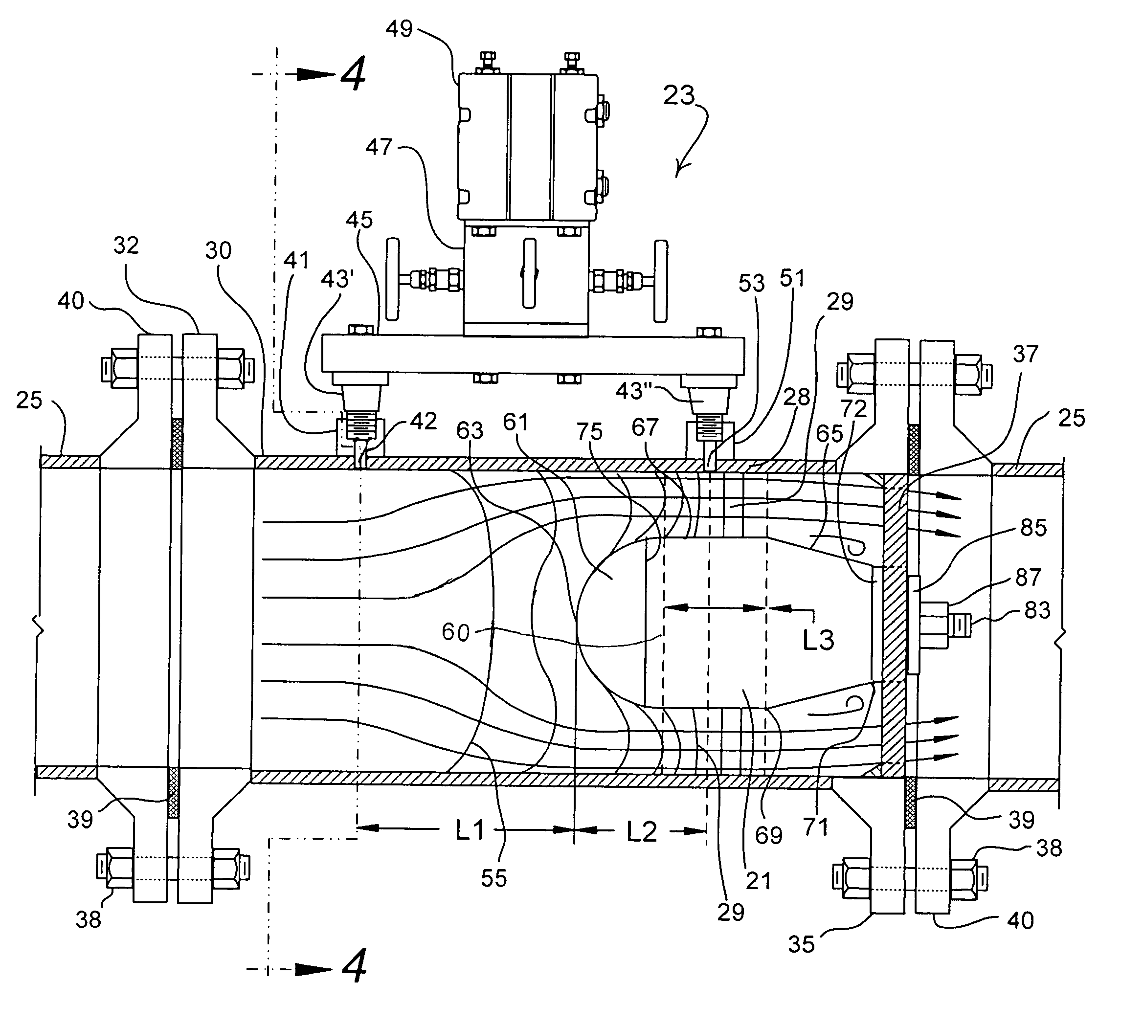
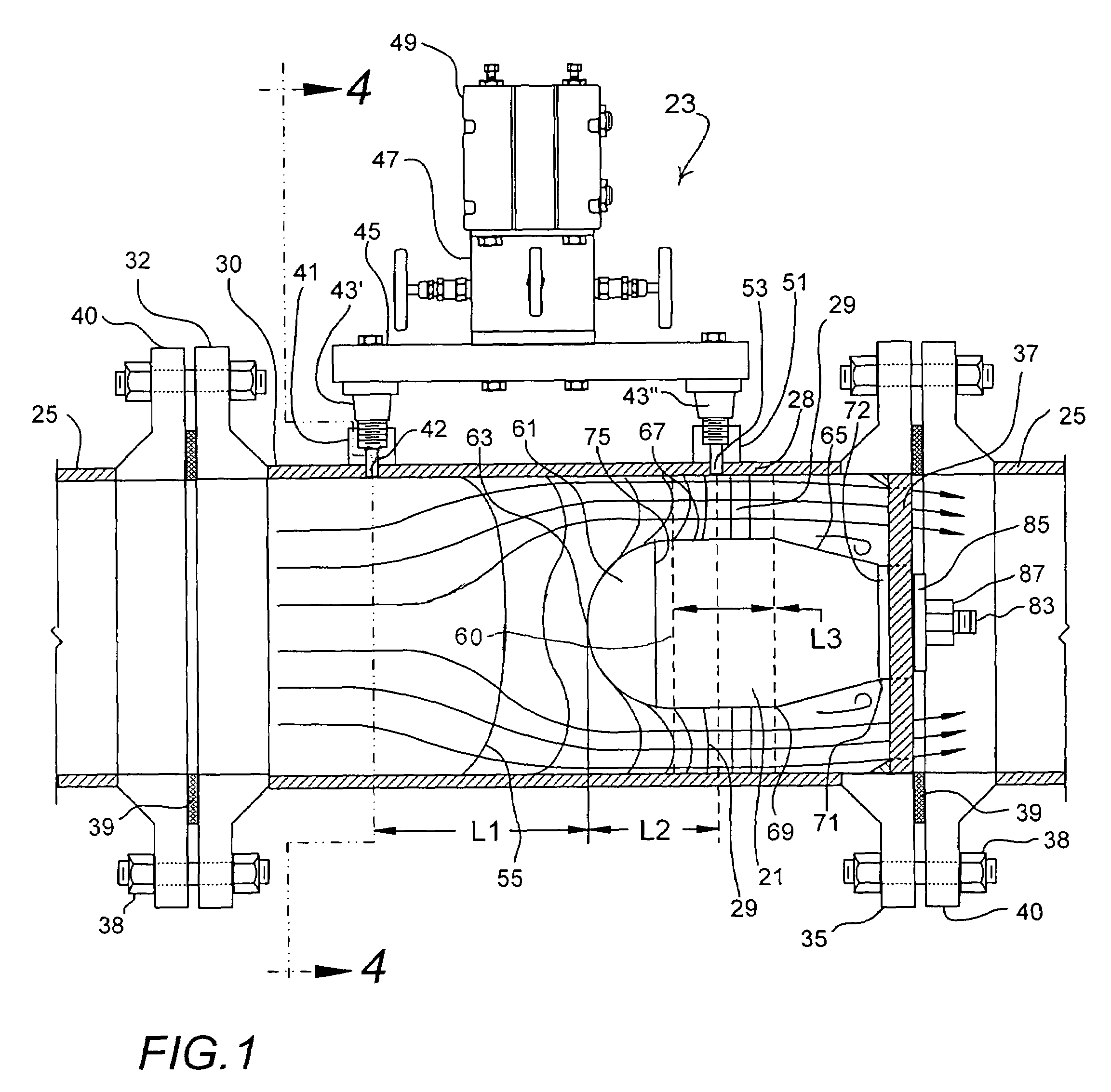
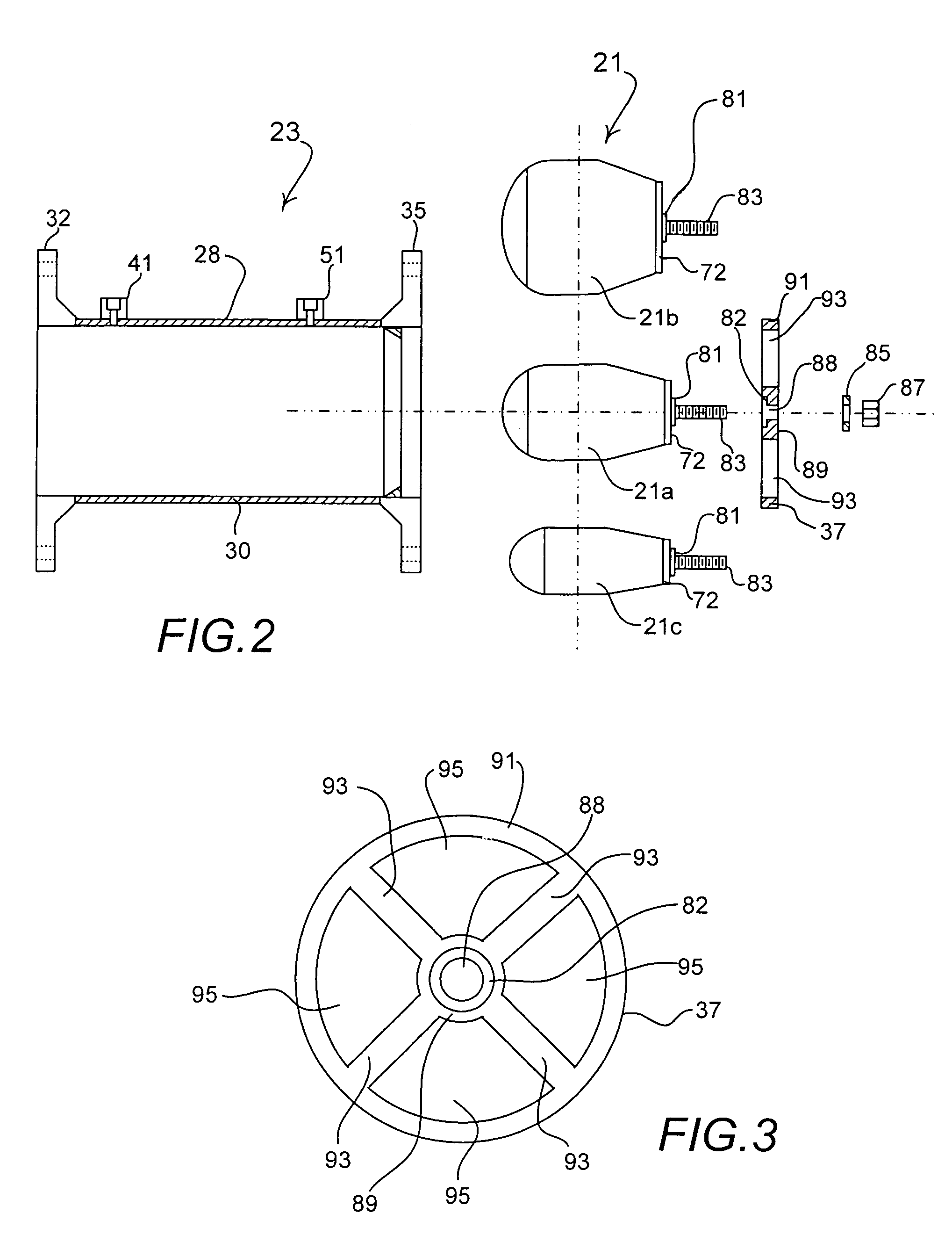
[0039]FIG. 1 shows the now preferred embodiment of device 21 of this invention in installation 23 of this invention maintained in conduit 25. Installation 23 includes pipe or conduit section 28 affixed between sections of conduit 25. Device 21 is concentrically located in the otherwise unobstructed flow path defined by pipe section 28 and obstructs fluid flow thereat to establish annular flow therearound. As may be appreciated, the diameter of pipe section 28 is constant (i.e., corresponding to conduit 25 and without significant pipe wall constriction or expansion along its length), the outside diameter of annular flow path 29 established by device 28 being substantially equivalent to the diameter of pipe section 28, while the inside diameter of annular flow path 29 is variable with contours of device 21.

[0040]Pipe section 28 includes a length of pipe 30 held between (welded for example) means of attachment in conduit 25 (as shown in FIG. 1, flanges 32 and 35 welded to pipe 30, thou...


PUM


Abstract

Differential pressure measurement devices, installations and methods are disclosed, the devices including a main body and retainer. The main body is characterized by a front portion having a substantially constant curvilinear flow facing front surface, a rear portion, and a substantially constant diameter portion between the front portion and the rear portion. The rear portion includes relatively larger and smaller diameter termini. The installation of this invention is maintained in a fluid flow containing conduit and includes a pipe section affixed between sections of the conduit. The device is concentrically located in the otherwise unobstructed flow path defined by the pipe section, with the device retainer downstream of all measurement ports, and obstructs fluid flow thereat to establish annular flow therearound having predictable characteristics.

Description

FIELD OF THE INVENTION[0001]This invention relates to fluid flow measurement systems, and, more particularly, relates to annular flow measurement devices and methods.BACKGROUND OF THE INVENTION[0002]Annular flow meters have been heretofore suggested and / or utilized (see U.S. Pat. Nos. 3,196,680, 4,638,672 and 1,126,275). These flow meters utilize a central disk or cone mounted in a pipe or conduit to divert fluid flow to the outside of the meter to produce a measurable differential pressure. Annular meters have the advantage of providing free drainage for heavy materials at the bottom of the pipe while at the same time, allowing lighter fluids to pass along the top of the pipe.[0003]Use of such devices often requires that the accuracy, specifications, features, and installation requirements be confirmed with the manufacturer, which in many cases lack documentation as to their accuracy and performance characteristics, and requires a flow test calibration to determine an accurate flow...

Claims


Application Information

Patent Timeline
Patent Type & Authority Patents(United States)
IPC IPC(8): G01F1/37
CPCG01F1/40
Inventor GOOD, FRED P.HARMAN, ERIC J.BALU, THOMAS A.
Owner VERIS
Why Eureka
Try Eureka