Paring apparatus with pivotable paring head

Active Publication Date: 2006-05-23
PF SCHWEISSTECH
View PDF14 Cites 6 Cited by
  • Summary
  • Abstract
  • Description
  • Claims
  • Application Information

AI Technical Summary

Benefits of technology

[0010]The pivotability of the paring head with respect to the paring head unit makes it possible for the guide element or elements of the guide assembly to be oriented tangentially relative to the surface so that the paring blade can always penetrate into the material of the tubular article to be pared. In that way it is possible, even when dealing with severely deformed tubular articles, to carry out a paring operation on the article, at raised portions or recesses.
[0039]Besides the pivotal movement about the pivot axis the paring head can also be adapted to be pivotable or tiltable about a further pivot axis or tilt axis. That further pivot or tilt axis extends substantially parallel to the plane defined by the support unit and the paring unit, that is to say that tilt axis extends tangentially relative to the article to be pared. This further pivotability or tiltability which can also be provided independently of the pivotability of the paring head about the pivot axis which extends perpendicularly to that of the paring unit and the support unit, is advantageous in particular when the article to be pared has a slight curvature along its longitudinal central axis.

Problems solved by technology

That procedure results in the removal of dirt inclusions from the manufacturing process and ageing-induced changes in the material, which can occur for example due to UV-damage or weathering at the surface and which would otherwise result in unsatisfactory welding results.
If the blade is wrongly oriented, frequently an only inadequate machining quality is achieved.
Then, either too much material is removed from the articles to be machined, whereby for example in the case of tubes the remaining cross-section is possibly unacceptably reduced, or the surface layers which are damaged due to dirt inclusions or ageing are not completely removed.
If the blade is oriented in an inclined manner, it is then possible that unwanted grooves or channels are left behind on the article to be pared, and they can adversely affect the welding.
Tubular rolled coil material, due to the manner of manufacture involved, has a certain degree of ovality which also occurs in the case of tubular bar material due to prolonged storage times. That tube ovality is unwanted in the paring operation as, with a fixedly set spacing between the support unit and the paring unit, with the blade arranged thereon, the removal of material becomes irregular and untidy so that it is not possible to achieve satisfactory machining results.
In extreme cases regions of the tube can remain unmachined while other regions of the tube are shaved off to an unacceptably great depth.
In the case of severely deformed tubes, however, unpared locations still remain behind even when using that paring apparatus.

Method used


Image

  • Paring apparatus with pivotable paring head
  • Paring apparatus with pivotable paring head
  • Paring apparatus with pivotable paring head

Examples


Embodiment Construction

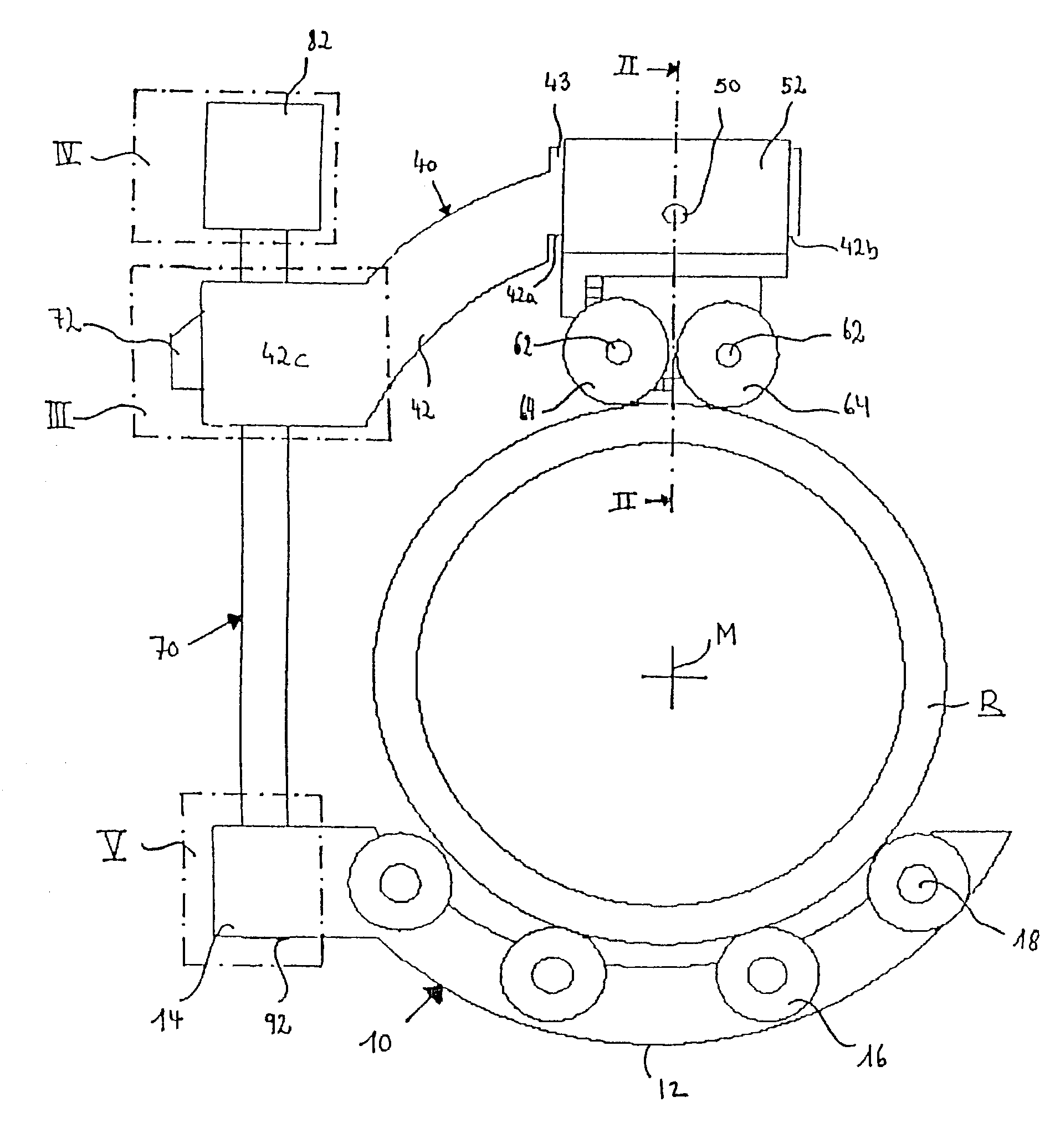
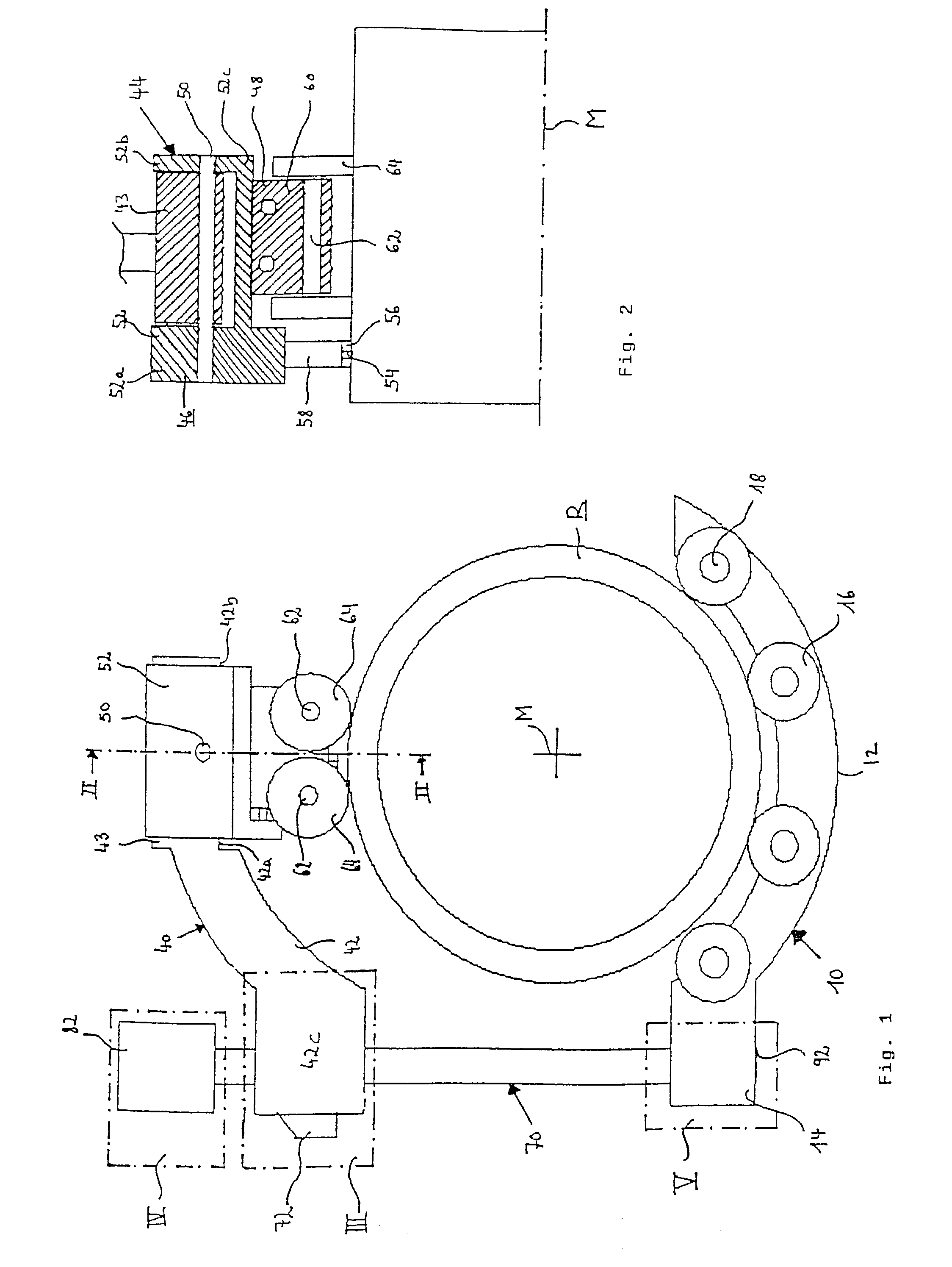
[0048]The paring apparatus according to the invention has as essential structural and functional units a support unit 10, a paring unit 40 and a carrier unit 70. The support unit 10 and the paring unit 40 are held to the carrier unit 70 in such a way that the support unit 10 and the paring unit 40 are at a spacing relative to each other and define between them a plane in which, during use of the paring apparatus, the article R to be pared is arranged. In the illustrated embodiment the article R to be pared is a plastic tube.

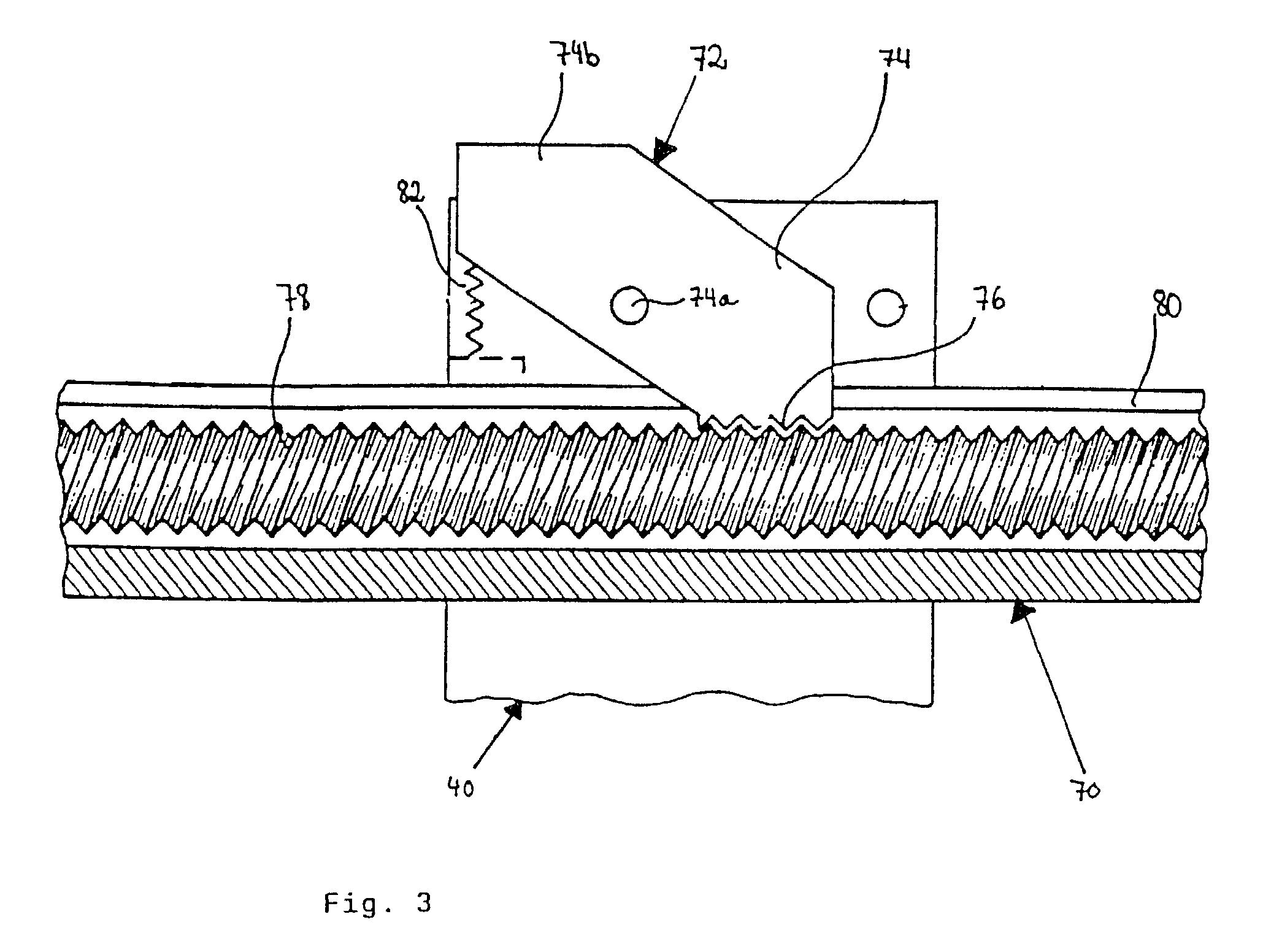
[0049]For the purposes of adjusting the spacing between the support unit 10 and the paring unit 40 the carrier unit 70 is provided with a spindle drive which is described in greater detail hereinafter. In this case the spacing between the support unit 10 and the paring unit 40 is determined by the diameter of the tubular article R to be pared.

[0050]The support unit 10 firstly has a carrier arm 12 which is approximately in the shape of a circular arc. At the left-...


PUM

PropertyMeasurementUnit
Elasticityaaaaaaaaaa
Resilienceaaaaaaaaaa
Sliding frictionaaaaaaaaaa

Abstract

An apparatus for paring tubular articles (R), especially for plastic tubes, has at least one support unit (10) for supporting the article (R) to be pared, a paring unit (40) which has a paring head (44) with at least one blade assembly (46) and at least one guide assembly (48), and a carrier unit (70) to which the support unit (10) and the paring head unit (40) are held in mutually spaced relationship. The paring head (44) is pivotable about a pivot axis (50) which extends at least approximately perpendicularly to the plane defined by the support unit (10) and the paring unit (40).

Description

[0001]The invention relates to an apparatus for paring tubular articles, especially plastic tubes.BACKGROUND OF THE ART[0002]The surfaces of tubes, cables or cylindrical bars frequently require machining prior to further processing thereof. Thus for example in the case of cables it is necessary to remove an insulating layer while when welding plastic tubes the surface of the tubes has to be shaved off prior to the welding operation. In that situation a layer of the order of magnitude of between about 0.5 mm and 0.3 mm (and even deeper, in dependence on large tubes) is removed in the regions which are to be welded together. That procedure results in the removal of dirt inclusions from the manufacturing process and ageing-induced changes in the material, which can occur for example due to UV-damage or weathering at the surface and which would otherwise result in unsatisfactory welding results.[0003]In order to be able to precisely remove a surface layer which is as thin as possible fr...

Claims


Application Information

Patent Timeline
IPC IPC(8): B23B3/00B23B5/16B23D21/10
CPCB23B5/16B23D21/10B23B2260/116Y10T82/16442Y10T82/22
Inventor MERLE, BERND
Owner PF SCHWEISSTECH
Why Eureka
Try Eureka