Method and apparatus for removing obstructions in the mines

a mine and obstruction technology, applied in the direction of ammunition, weapons components, ammunition projectiles, etc., can solve the problems of oversized and/or unstable rock masses, adits, stop, drawpoints, etc., and achieves simple and safe use, cost-effective, and robust construction

Inactive Publication Date: 2006-05-23
ROCKTEK
View PDF47 Cites 7 Cited by
  • Summary
  • Abstract
  • Description
  • Claims
  • Application Information

AI Technical Summary

Benefits of technology

[0011](b) a tube for launching the projectile. The system is simple and safe to use, cost-effective, of robust construction and highly effective and efficient in removing obstructions and enables accurate and remote shooting of rock masses, even of high rock hangups.
[0012]The body of the projectile contains a detonating device having a detonator inserted into its front end, a striker in its rear end, and a primer located between the detonator and striker. The striker and primer are separated from one another by a spring member which forces the striker away from the primer and a safety pin which restricts the motion of the striker towards the primer during shipping. The safety pin is removed before the launch of the projectile to permit the striker to impact the primer upon impact of the projectile with the rock face. Upon impact with the rock, the striker is forced forward with a sufficient force to overcome the resistive force of the spring and impact and ignite the primer which in turn ignites the detonator. The safety pin can be highly effective in preventing misfires of the detonating device during projectile assembly.
[0017]The detonating device is received in a pocket in the body that permits the detonating device to move longitudinally and latitudinally in response to movement of the projectile. In this manner, the possibility of a misfire is significantly reduced, even at low flight velocities. The movement of the detonating device within the pocket will permit the striker to more readily impact the primer.
[0029]Aiming of the device underground or at night is relatively straightforward. A radiation emitting device, such as a flashlight or laser, is detachably mounted onto the tube and a light beam from the device is aligned with the desired target area to align the launching tube with the target. This methodology is highly accurate and reduces the likelihood that the projectile will miss the target area.

Problems solved by technology

In mining applications, it is common to encounter rock blockages of mine openings, such as shafts, adits, stops, drawpoints, and drifts, and oversized and / or unstable rock masses such as in large surface mining and quarrying operations.
Such rock masses can interrupt production and pose an unsafe condition for employees.
The removal of such rock masses is not only extremely hazardous but also difficult.
People have been killed or seriously injured while performing these steps.
Third, the system must have a low rate of misfires.
Fourth, the projectile fired from the system should disintegrate upon impact in the event that a misfire occurs and thereby dissipate the explosive charge and render harmless the undetonated explosive charge.

Method used


Image

  • Method and apparatus for removing obstructions in the mines
  • Method and apparatus for removing obstructions in the mines
  • Method and apparatus for removing obstructions in the mines

Examples


Embodiment Construction

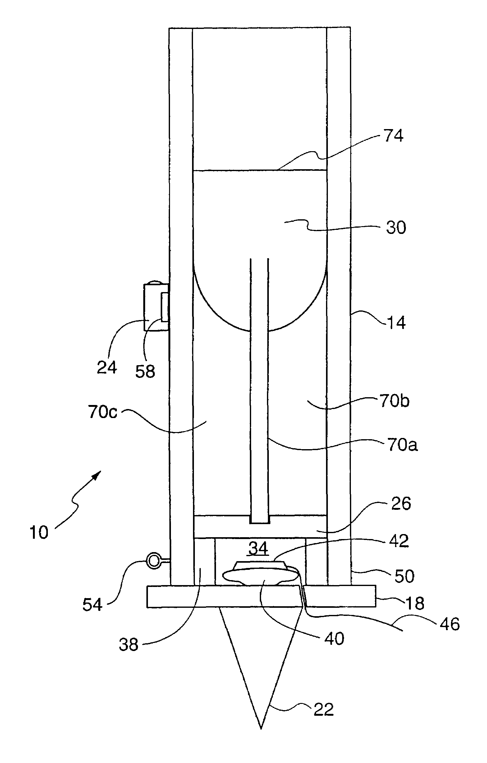
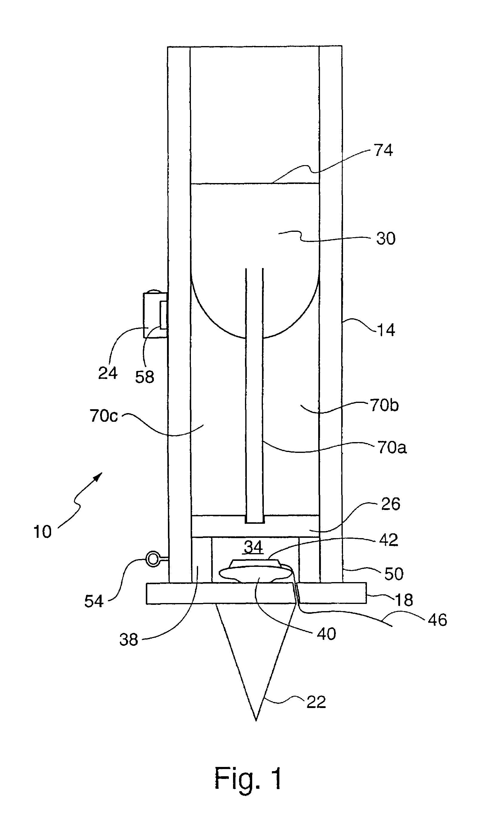
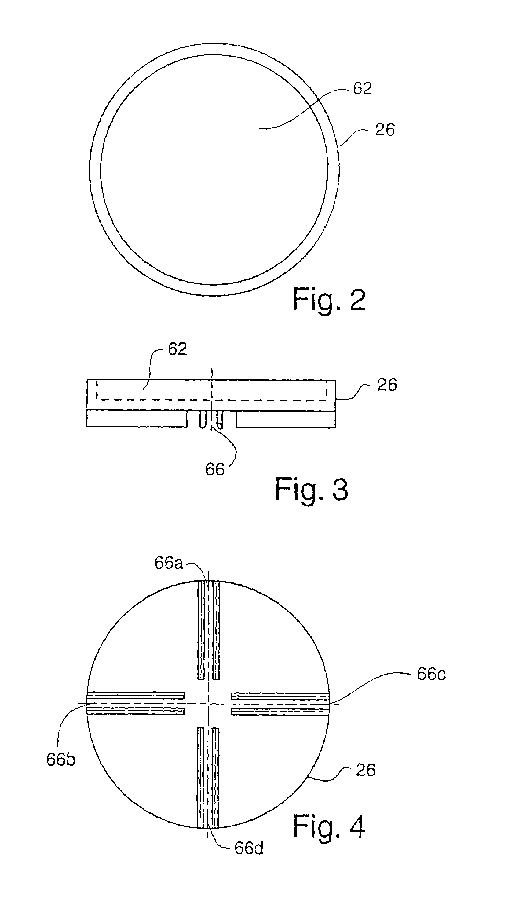
[0050]Referring to FIGS. 1 and 9–11, a system 10 according to the present invention includes a launching tube 14, a base 18, an anchor spike 22, an aiming device 24, a pusher plate 26, and a projectile 30.

[0051]The base 18 further includes a cavity 34 located beneath the projectile 30 and pusher plate 26 containing a propelling charge 40 for launching the projectile 30 from the launching tube 14. The cavity 34 is formed by an inner tube 38 positioned inside of the launching tube 14 such that the walls of the inner tube 38 support the pusher plate 26. Accordingly, the outer diameter of the inner tube 38 is the same or less than the outer diameter of the pusher plate 26.

[0052]The propelling charge 40 is formed by an energetic material, such as a pyrotechnic (e.g., black powder) or a propellant, contained within a fabric, paper, and / or plastic pouch that is antistatic and / or water / moisture resistant. The pouch has a slit or pocket 42 into which an initiator is inserted. The initiator 4...


PUM


Abstract

The present invention is directed to a system for fragmenting rock obstacles and obstructions in mines. The system uses a projectile having a flat or concave nose and a detonating device that has a safety pin to prevent a striker from prematurely igniting the primer during handling of the projectile. The primer is designed to initiate a detonator which detonates an explosive charge upon impact of the projectile with the target rock. The system can include transmitters and receivers and counters to provide remote operation of projectile launch, prearming, arming and / or detonation.

Description

CROSS REFERENCE TO RELATED APPLICATIONS[0001]The present application is a divisional application of U.S. application Ser. No. 09 / 173,876, filed Oct. 16, 1998 now U.S. Pat. No. 6,457,416, and entitled “Method and Apparatus for Removing Obstructions in Mines”, which claims priority both from U.S. Provisional Patent Application Ser. No. 60 / 062,537, filed Oct. 17, 1997, and entitled “A Method and Apparatus for Removing Draw Point Blockages, Scaling Unstable Rock Formations and Breaking Free-Standing Boulders” and from U.S. Provisional Patent Application Ser. No. 60 / 087,058, filed May 28, 1998, and entitled “Method and Apparatus for Removing Obstructions in Mines,” which are incorporated fully herein in their entireties.FIELD OF THE INVENTION[0002]The present invention is directed generally to a method and apparatus for removing obstructions in mines and specifically to a system for removing rock blockages and / or oversized and / or unstable rock masses in mines and other types of excavatio...

Claims


Application Information

Patent Timeline
Patent Type & Authority Patents(United States)
IPC IPC(8): F42B10/00F42B12/20F42D3/00
CPCF42D3/00F42B12/204F42D1/00
Inventor MICKE, BRIAN P.GAVRILOVIC, MIHAILOWRIGHT, KEITH W.
Owner ROCKTEK
Why Eureka
Try Eureka