Exhaust gas purifying apparatus

a technology of exhaust gas and purification apparatus, which is applied in mechanical equipment, machines/engines, separation processes, etc., can solve the problems of insufficient purification rate and small contact area with exhaust gas, and achieve the effect of raising the purification ability of exhaust gas, suppressing the decrease of engine output, and increasing purification ra

Inactive Publication Date: 2006-05-23
CATALER CORP
View PDF21 Cites 7 Cited by
  • Summary
  • Abstract
  • Description
  • Claims
  • Application Information

AI Technical Summary

Benefits of technology

[0021]According to the first aspect of the present invention, the radial cross sectional area in the catalyst region of the first honeycomb catalyst portion is set in the 1 / 5–2 / 3 range with respect to the radial cross sectional area of the flowing way formed by the inwall surface of the first mounting position of the exhaust way, with the first honeycomb catalyst portion being removed. Therefore, it is possible to raise a purification ability of the exhaust gas while suppressing the decrease of the engine output.
[0022]According to the exhaust gas purifying apparatus of the present invention, the catalyst has: (1) the first honeycomb catalyst portion placed at the first mounting position of the exhaust way; and (2) the second honeycomb catalyst portion placed at the second mounting position of the exhaust way. The first honeycomb catalyst has the outer circumferential surface for forming the blowing passage with the inwall surface of the exhaust pipe, including the metallic first carrier with a plurality of holes being along a length direction of the exhaust way of the exhaust pipe. The second honeycomb catalyst portion includes the metallic second carrier with a plurality of holes being along a length direction of the exhaust way of the exhaust pipe. The radial cross sectional area in the catalyst region of the first honeycomb catalyst portion is set in the 1 / 5–2 / 3 range with respect to the radial cross sectional area of the flowing way defined by the inwall surface of the first mounting position of the exhaust way with the first honeycomb catalyst portion being removed.
[0023]Accordingly, the exhaust gas discharged from the exhaust port of the engine can be purified in both of the first honeycomb catalyst portion and the second honeycomb catalyst portion; so, the purification rate is higher. The exhaust gas discharged from the exhaust port of the engine is divided into: (1) one flow which runs through the blowing passage to the second honeycomb catalyst portion without running through the holes of the first honeycomb catalyst portion; and (2) the other flow which runs through the holes of the first honeycomb catalyst portion into the second honeycomb catalyst portion. This can ensure a flow quantity of the exhaust gas by the blowing passage to suppress the decrease of the engine output. This can ensure a purification ability, since the exhaust gas runs through the blowing passage formed at the outer circumferential surface of the first honeycomb catalyst portion into the second honeycomb catalyst portion placed at the downstream side.
[0024]The carrier of the first honeycomb catalyst portions being formed of metal, can increase an area for reacting with the exhaust gas to ensure a flow area of holes in comparison with a ceramic carrier. This can decrease a passage resistance of the exhaust gas. Also, this can advantageously prevent a pressure loss so as to improve the engine output even in the case where the first honeycomb catalyst portion is near to the exhaust port of the engine.
[0025]The exhaust gas, having high-temperature, runs through the first honeycomb catalyst portion being near to the exhaust port of the engine. Accordingly, although the first honeycomb catalyst portion has a small reaction-area owing to the blowing passage, it can ensure the purification rate. Further, the carrier of the first honeycomb catalyst portion, being near to the exhaust port of the engine, is to be in high-temperature: the carrier of the first honeycomb catalyst portion is formed of metal to improve a heat conduction quantity. So, the carrier of the first honeycomb catalyst portion can advantageously increase a thermal conduction quantity to the exhaust pipe so as to suppress a thermal damage of the first honeycomb catalyst portion.
[0026]The second honeycomb catalyst portion, is far from the exhaust port of the engine in comparison to the first honeycomb catalyst portion. So, the temperature of the exhaust gas is to be decreased in the second honeycomb catalyst portion. However, the exhaust gas is heated in temperature by catalytic reaction in the first honeycomb catalyst portion, and the heated exhaust gas runs into the inlet of the holes of the second honeycomb catalyst portion. So, the exhaust gas flowing into the inlet of the second honeycomb catalyst portion is advantageously high in temperature, thereby raising a purification rate of the exhaust gas in the second honeycomb catalyst portion.

Problems solved by technology

In addition, according to the cylindrical catalyst used in the conventional technique, since it is formed of the punching tube retaining the catalyst component, the contact area with exhaust gas is small, and the purification rate is not sufficient.
In addition, the pre-catalyst 300 formed of the honeycomb catalyst is near to the exhaust port of the engine to generate thermal problems of the pre-catalyst 300, being in high temperatures.

Method used


Image

  • Exhaust gas purifying apparatus
  • Exhaust gas purifying apparatus
  • Exhaust gas purifying apparatus

Examples


embodiment 1

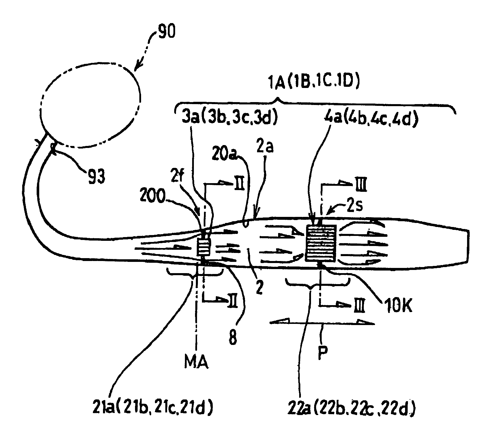
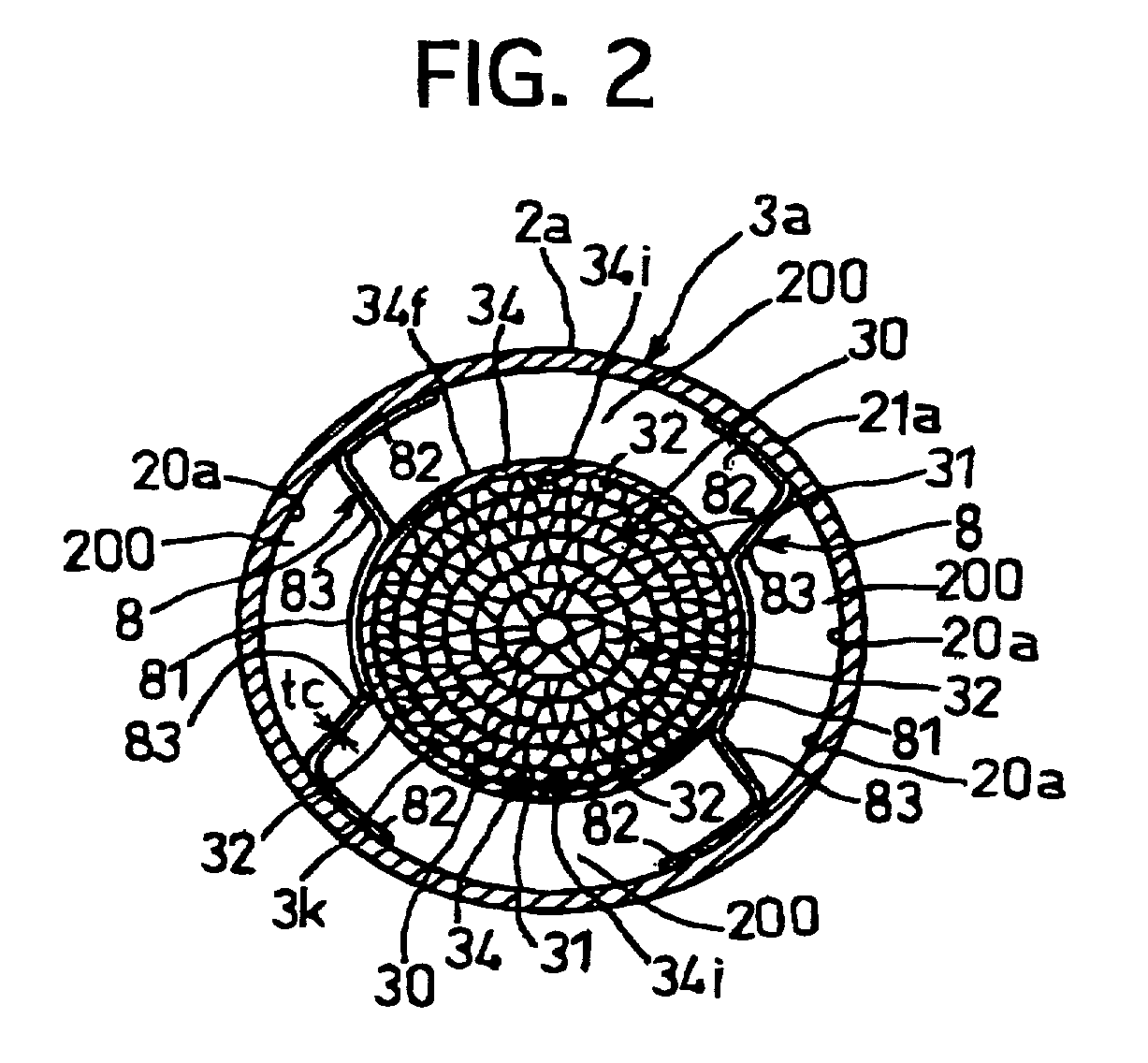
[0056]FIG. 1 illustrates an exhaust gas purifying apparatus 1A of Embodiment 1. The exhaust gas purifying apparatus 1A is applied to a 2-stroke cycle engine 90 of a motorcycle. This apparatus 1A has an exhaust pipe 2a, a first honeycomb catalyst portion 3a, and a second honeycomb catalyst portion 4a. The exhaust pipe 2a forms an exhaust way 2 communicated with the exhaust port 93 of the 2-stroke cycle engine 90. The fist honeycomb catalyst portion 3a is placed in a first mounting position 2f of a small diameter portion (the first catalyst region) 21a formed at an upstream side of the exhaust way 2. The second honeycomb catalyst portion 4a is placed in the second mounting position 2s of a large diameter portion 22a (the second catalyst region) formed at a downstream side separated at a predetermined distance from the small diameter portion 21a in a longitudinal direction “P” of the exhaust pipes 2.

[0057]That is to say, the exhaust way 2 of the exhaust pipe 2a has the small diameter p...

embodiment 2

[0078]Embodiment 2 is substantially the same as Embodiment 1 in construction, function and effect. The surroundings of difference will be hereinafter described. FIG. 1 illustrates an exhaust gas purifying apparatus 1B of Embodiment 2. The exhaust gas purifying apparatus 1B has an exhaust pipe 2a, a first honeycomb catalyst portion 3b, and a second honeycomb catalyst portion 4b. The exhaust pipe 2a forms the exhaust way 2 communicated with the exhaust port 93 of the 2-stroke cycle engine 90. The first honeycomb catalyst portion 3b is placed in a first mounting position 2f of a small diameter portion (the first catalyst region) 21b formed at the upstream side of the exhaust way 2. The second honeycomb catalyst portion 4b is placed in a second mounting position 2s of a large diameter portion 22b (the second catalyst region) formed at the downstream side separated at a predetermined distance from the small diameter portion 21b in a longitudinal direction “P” of the exhaust pipes 2a.

[00...

embodiment 3

[0081]Embodiment 3 is substantially the same as Embodiment 1 in construction, function and effect. The surroundings of difference will be hereinafter described. FIG. 1 also illustrates an exhaust gas purifying apparatus 1C of Embodiment 3. The exhaust gas purifying apparatus 1C has an exhaust pipe 2a, a first honeycomb catalyst portion 3c, and a second honeycomb catalyst portion 4c. The exhaust pipe 2a forms the exhaust way 2 communicated with the exhaust port 93 of the 2-stroke cycle engine 90. The first honeycomb catalyst portion 3c is placed in a first mounting position 2f of a small diameter portion (the first catalyst region) 21c formed at the upstream side of the exhaust way 2. The second honeycomb catalyst portion 4c is placed in the second mounting position 2s of a large diameter portion 22c (the second catalyst region) formed at the downstream side separated at a predetermined distance from the outlet of the small diameter portion 21c in a longitudinal direction “P” of the ...


PUM

PropertyMeasurementUnit
diameteraaaaaaaaaa
inner diameteraaaaaaaaaa
outer diameteraaaaaaaaaa

Abstract

An exhaust gas purifying apparatus includes an exhaust pipe 2a for forming an exhaust way 2, and a catalyst disposed in the exhaust way 2 for purifying an exhaust gas. The catalyst includes the first honeycomb catalyst portion 3a and the second honeycomb catalyst portion 4a. The first honeycomb catalyst portion 3a has an outer circumferrencial surface for forming a blowing passage 200 with an inner circumferrencial surface of the exhaust pipe 2a. The radial cross sectional area in the catalyst region of the first honeycomb catalyst portion 3a is set in the 1/5–2/3 range with respect to the radial cross sectional area of a flowing way defined by the inwall surface of the first mounting position 3a placed in the exhaust way 2, with the first honeycomb catalyst portion 3a being removed.

Description

BACKGROUND OF THE INVENTION[0001]1. Field of the Invention[0002]The present invention relates to an exhaust gas purifying apparatus containing an exhaust pipe for forming an exhaust way communicated with an exhaust port of an engine, and a catalyst disposed in the exhaust way for purifying exhaust gas.[0003]2. Description of the Related Art[0004]Conventionally, in a small size engine such as a motorcycle engine, a cylindrical catalyst is used for purifying exhaust gas discharged from an exhaust port of a motorcycle engine to an exhaust way of an exhaust pipe. This cylindrical catalyst contains a punching tube with a center hole and a catalyst component retained on the punching tube. This cylindrical catalyst is disposed to cover an inwall surface of the exhaust way for gaining an engine output sufficiently. This cylindrical catalyst is high in a blowing rate so as to suppress a pressure loss for ensuring the engine output. This cylindrical catalyst, however, is a small area to react...

Claims


Application Information

Patent Timeline
Patent Type & Authority Patents(United States)
IPC IPC(8): F01N3/28F01N3/20B01D53/86F01N3/24F01N13/02
CPCF01N3/28F01N13/0097F01N3/2885
Inventor SHIRAHATA, JUNYASATO, MASAYASUOZAWA, TERUHIKO
Owner CATALER CORP
Why Eureka
Try Eureka