Circuit arrangement and method for an illumination device having settable color and brightness

a technology of illumination device and circuit arrangement, applied in the direction of constant-current supply dc circuit, electric variable regulation, fishing, etc., can solve the problems of inability to set color and brightness easily without additional, and require a considerable amount of investment, and achieve the effect of low investmen

Inactive Publication Date: 2006-05-23
PATENT TREUHAND GESELLSCHAFT FUR ELECTRIC GLUEHLAMPEN MBH
View PDF10 Cites 14 Cited by
  • Summary
  • Abstract
  • Description
  • Claims
  • Application Information

AI Technical Summary

Benefits of technology

[0007]The object of the present invention is to provide a circuit arrangement which accomplishes the setting of color and brightness of an illumination device with low outlay.

Problems solved by technology

In the prior art, it has proved disadvantageous that considerable outlay is required to provide the above-described luminous colors, and that setting color and brightness easily is impossible without additional outlay.

Method used


Image

  • Circuit arrangement and method for an illumination device having settable color and brightness
  • Circuit arrangement and method for an illumination device having settable color and brightness
  • Circuit arrangement and method for an illumination device having settable color and brightness

Examples


Embodiment Construction

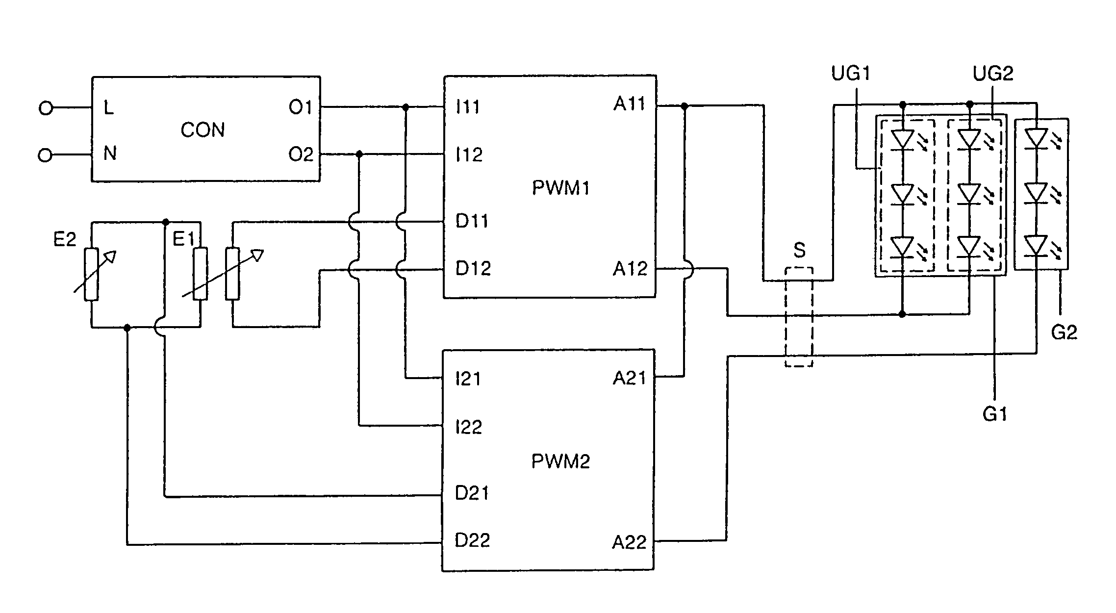
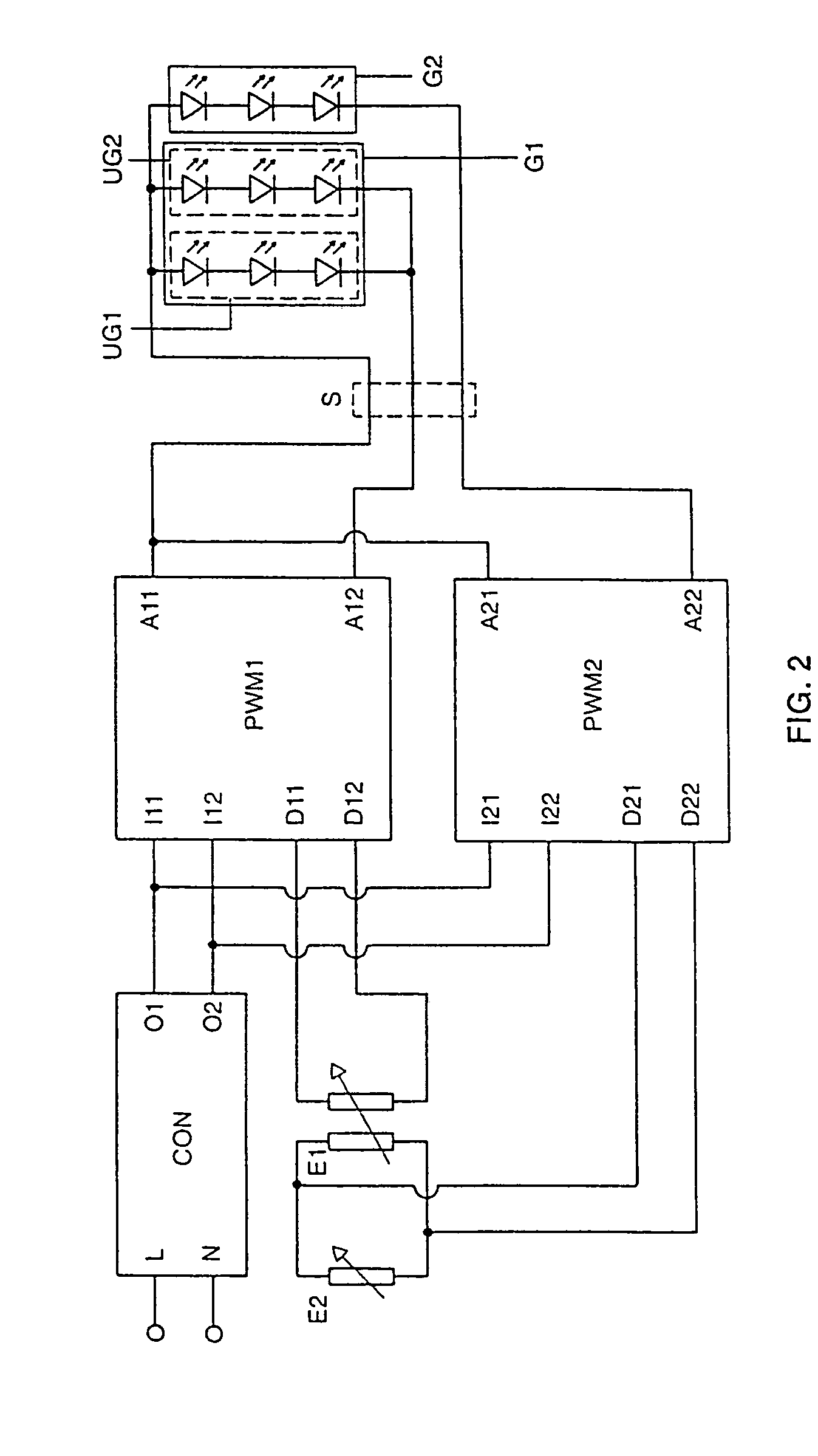
[0032]FIG. 2 shows a block diagram of a preferred embodiment of the invention. The block diagram shows a preferred embodiment of a circuit arrangement having light sources connected.

[0033]A voltage transformer CON draws power, via terminals L and N, from a power source (not shown) which is, for example, in the form of a mains voltage or a battery. The voltage transformer CON provides an operating voltage at its terminals O1 and O2, which is suitable for operating light sources connected to the circuit arrangement.

[0034]The operating voltage is fed in to a first and a second dimming device (PWM1, PWM2) via the terminals Ill and I12 and, respectively, I21 and I22. The first dimming device PWM1 has two terminals A11 and A12 to which a first group G1 of light sources is connected. The second dimming device PWM2 has two terminals A21 and A22 to which a second group G2 of light sources is connected.

[0035]In the exemplary embodiment illustrated, the terminal A21 is connected to the termina...


PUM


Abstract

It is intended to be possible to use a respective setting apparatus (E1, E2) to set the color and the brightness of an illumination device separately. Light sources having three different colors are operated for this purpose. Only one first power supply (CON, PWM1) is provided for two colors, whereas the third color is supplied by a second power supply (CON, PWM2). The brightness can be set by altering the power output of the first (CON, PWM1) and the second (CON, PWM2) power supplies at the same time. The color can be set by altering the power output of the second (CON, PWM2) power supply.

Description

FIELD OF THE INVENTION[0001]The invention relates to circuit arrangements which allow both the color and the brightness of radiated light to be set in an illumination device.BACKGROUND OF THE INVENTION[0002]The color of a light source, also referred to as the chromaticity in the literature, is generally determined using a standardized chromaticity diagram. This standardized chromaticity diagram is defined in the standard DIN 5033 or in the equivalent international standard CIE 1931. In the standardized chromaticity diagram, a color is determined by an x and a y coordinate. FIG. 1 shows a standardized chromaticity diagram. All colors visible to the human eye lie within a color triangle T. A so-called achromatic point U is determined by the coordinates x=0.33 and y=0.33. Colors in the region around the achromatic point U are generally perceived as white. The colors assumed by daylight during the course of a day lie on a so-called D line D.[0003]In order to provide an illumination devi...

Claims


Application Information

Patent Timeline
Patent Type & Authority Patents(United States)
IPC IPC(8): H05B37/00H05B37/02H05B44/00
CPCH05B33/0818H05B33/0863H05B37/02H05B33/0866Y02B20/346H05B45/24H05B45/20H05B45/37A01K97/04A01K97/06Y02B20/30
Inventor BOULOUEDNINE, MOURADFALLER, ALEXANDER
Owner PATENT TREUHAND GESELLSCHAFT FUR ELECTRIC GLUEHLAMPEN MBH
Why Eureka
Try Eureka