DC ground fault detection with resistive centering

a resistive centering and ground fault technology, applied in the direction of power supply testing, instruments, circuit testing, etc., can solve the problems of high electrical reliability and safety concerns of hybrid electric vehicles, many deaths due to ac systems, and early alternating-voltage systems that are somewhat dangerous to the publi

a resistive centering and ground fault technology, applied in the direction of power supply testing, instruments, circuit testing, etc., can solve the problems of high electrical reliability and safety concerns of hybrid electric vehicles, many deaths due to ac systems, and early alternating-voltage systems that are somewhat dangerous to the publi

US7049825B2Active Publication Date: 2006-05-23BAE SYSTEMS CONTROLS INC

Image

  • DC ground fault detection with resistive centering
  • DC ground fault detection with resistive centering
  • DC ground fault detection with resistive centering

Examples


Embodiment Construction

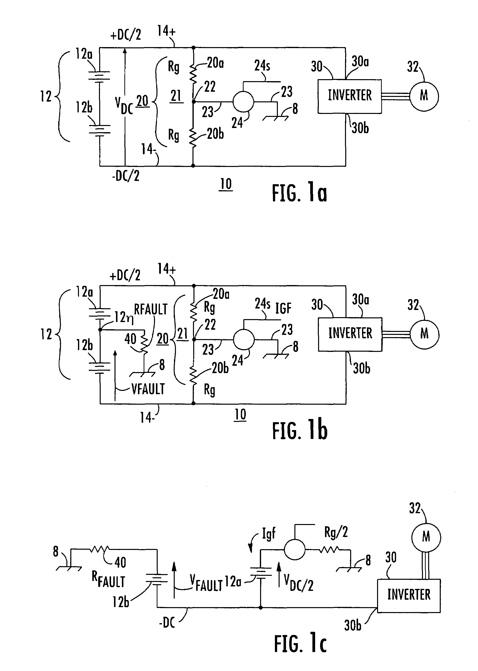
[0030]In FIG. 1a, a direct-voltage powered system is designated generally as 10. System 10 includes a direct voltage source designated generally as 12, which includes plural series-connected voltage sources illustrated as electrochemical batteries 12a and 12b. While only two such sources or batteries are illustrated, three or more batteries may be series-connected or stacked to generate the voltage of source 12. Also, while the sources are illustrated as batteries, they may instead be externally-powered electronic devices. The direct voltage source 12 produces its voltage “between” the positive terminal of source 12a and the negative terminal of source 12b. Those skilled in the art know that the term “between” has a meaning in electrical parlance which is different from its meaning in mechanics or topology. The voltage felt “across” the voltage source 12 is designated VDC, and is represented by an arrow with the arrowhead adjacent the positive terminal, all as is conventional in the...


PUM


Abstract

A method for determining the nature of a ground fault in a floating direct voltage load powering context includes measuring the load voltage and the current at a nominal balance point, both before and after closing a circuit to the load. The fault resistance and the fault voltage are determined as the solution to an equation in two unknowns given the conditions before and after application of load voltage or at least precharge.

Description

FIELD OF THE INVENTION[0001]This invention relates to electrical fault detection in the context of direct voltages, and more especially to detection of the resistance and voltage to a nominally isolated ground.BACKGROUND OF THE INVENTION[0002]In the early days of electrical power, direct and alternating voltage power systems competed in the marketplace. Due to the ability of magnetic transformers to adjust voltage up and down, and also possibly as a result of the forces of advertising, the use of alternating voltage for powering homes and factories superseded the use of direct voltage. Early alternating-voltage (also known as alternating current or AC) systems were somewhat dangerous to the public, because of the possibility the case of equipment connected to the power line could become energized in the event of an internal fault. In such a situation, the ground or earth became part of the electrical path, and someone who inadvertently came into contact with the case of the equipmen...

Claims


Application Information

Patent Timeline
23 May 2006
Publication
US7049825B2
IPC
G01R31/14; G01R27/08; G01R27/18; G01R31/02; G01R31/40
CPC
G01R27/18; G01R31/40; G01R31/024; G01R31/52
Inventors
CARRUTHERS, PETER ALEXANDER