On-vehicle video camera

a video camera and vehicle technology, applied in the field of vehicle video cameras, can solve the problems of video camera, unidentifiable captured objects, and insufficient mirrors to provide visibility of such areas

Inactive Publication Date: 2006-05-23
SONY CORP
View PDF4 Cites 38 Cited by
  • Summary
  • Abstract
  • Description
  • Claims
  • Application Information

AI Technical Summary

Benefits of technology

[0011]In the thus constructed video camera, the light emitting unit automatically emit

Problems solved by technology

In some kinds of vehicles, however, structurally, the above-noted mirrors may sometime be insufficient to provide visibility of such areas.
During night travel, however, a video camera is likely to capture an image in light as low as the video camera can, and the image displayed on a monitor would possibly make the captured object unidentifiable.
However, there is no light source for a video camera for use in applications other than a back monitor system which is turned on in response to the operation of the automobile, leading to a problem in that a video

Method used


Image

  • On-vehicle video camera
  • On-vehicle video camera
  • On-vehicle video camera

Examples


Embodiment Construction

[0021]A preferred embodiment of the present invention is hereinafter described with reference to the drawings.

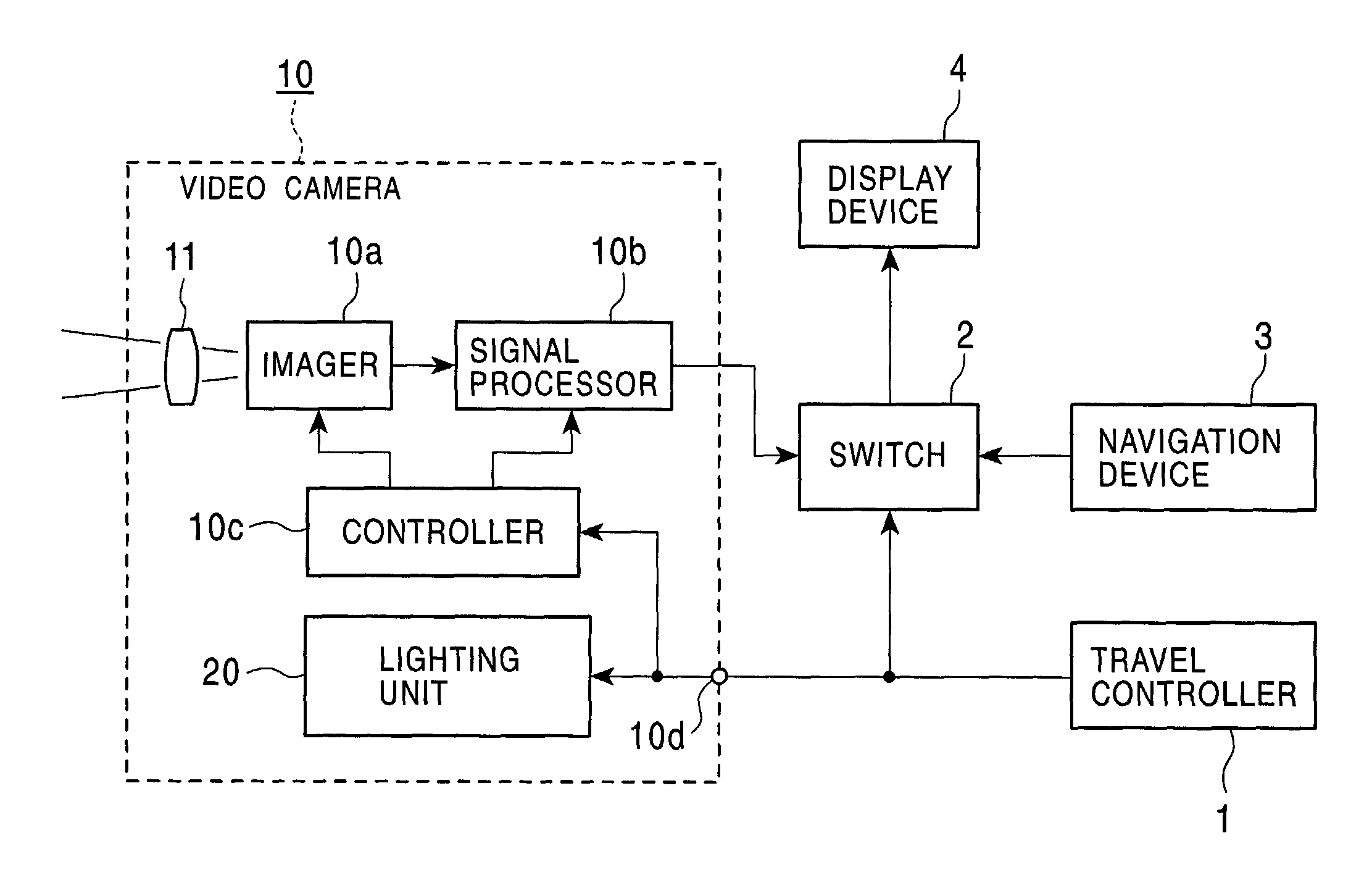
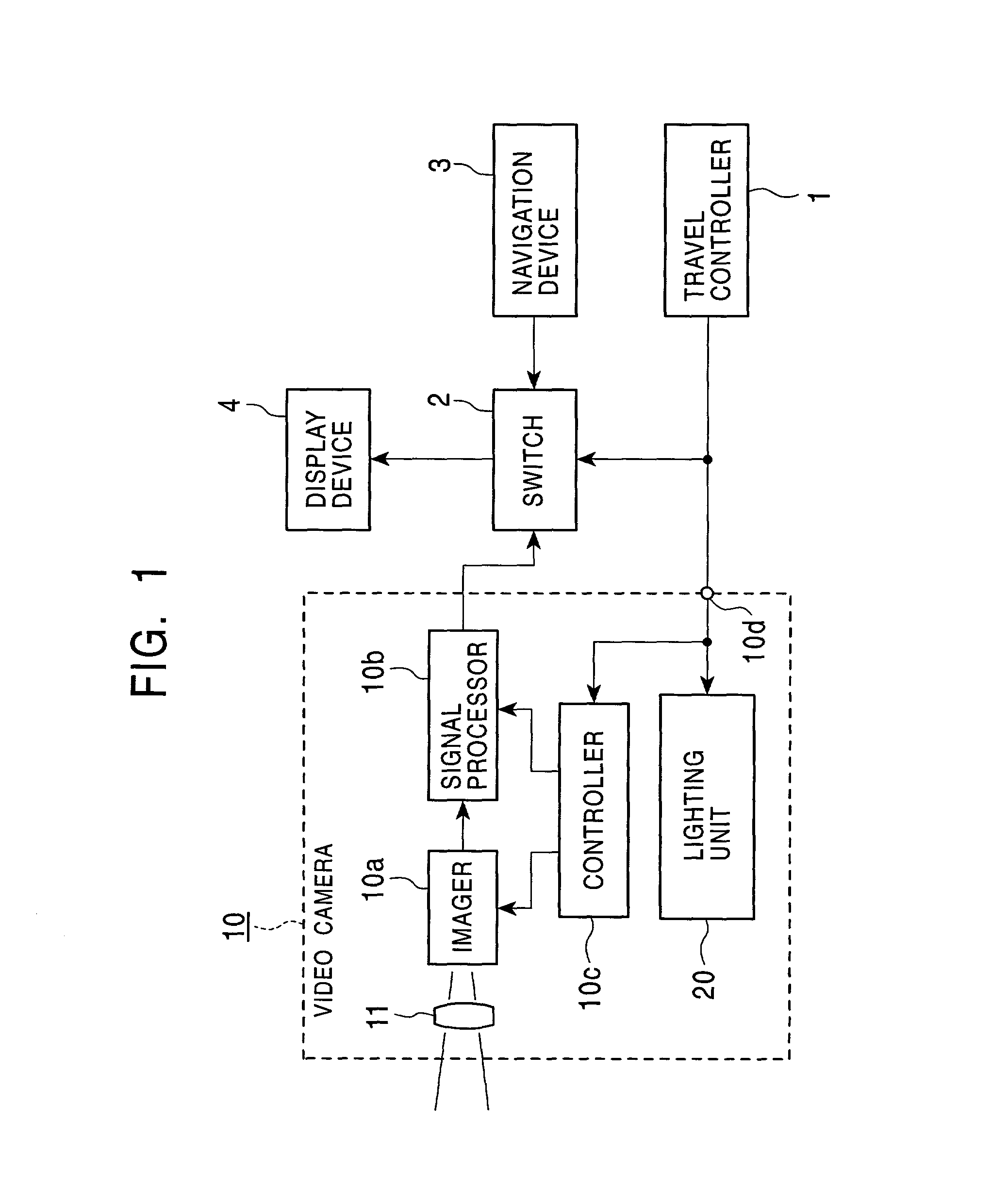
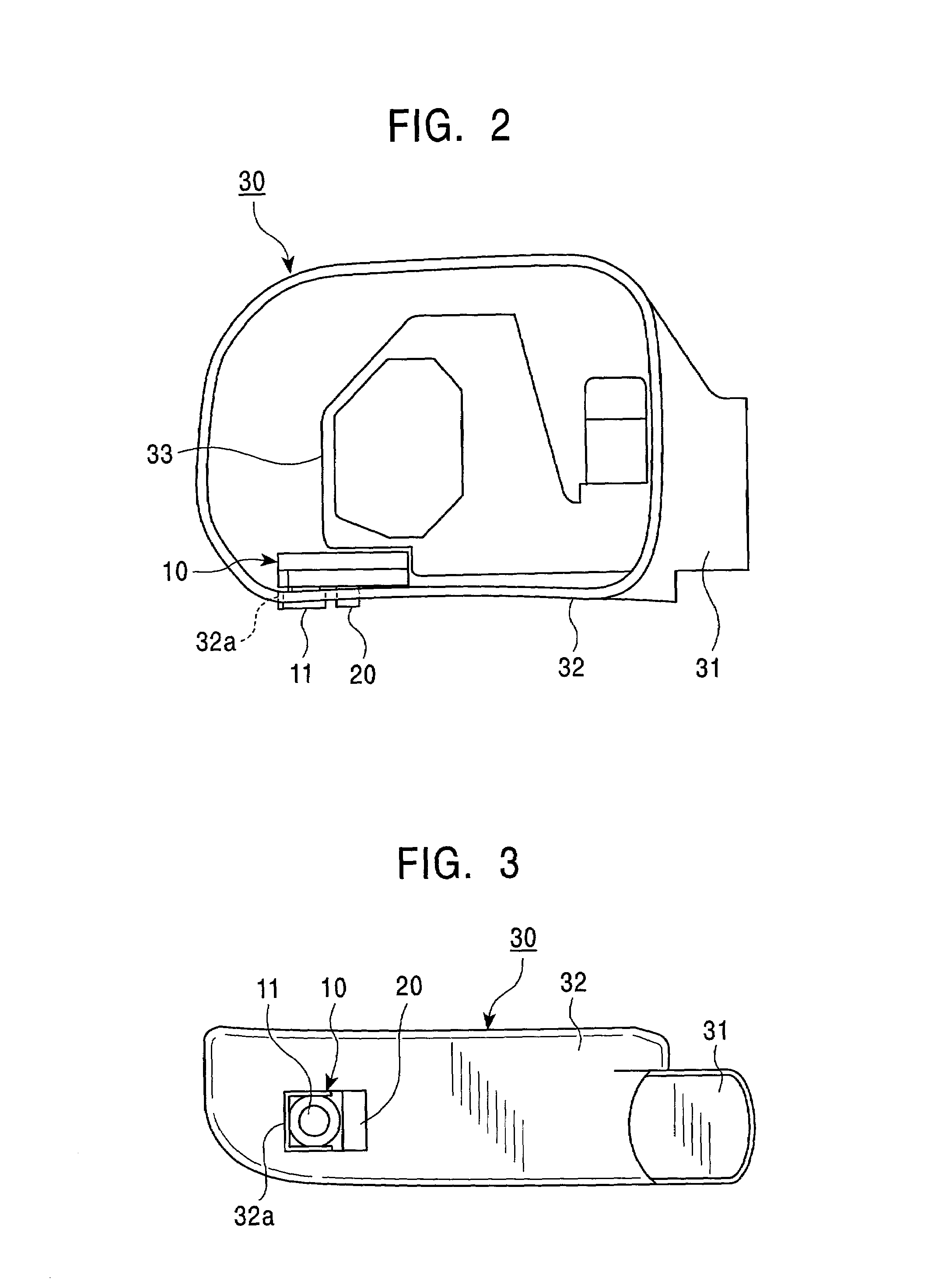
[0022]This embodiment provides an on-vehicle video camera mounted on an automobile which travels on the road. FIG. 1 shows the structure of an on-vehicle video camera 10 according to the present embodiment, and a system configuration of devices connected to the video camera 10. The video camera 10 is incorporated in one sideview mirror (outside mirror) positioned at either side of the automobile, as described later. The video camera 10 includes a lens 11 through which image light is focused onto an imager 10a, and the image light is converted into an electrical imaging signal in the imager 10a. The lens 11 may be a single focus lens capable of relatively wide angle photography. The imager 10a may be a CCD-type imaging device, a CMOS imaging device, or the like.

[0023]The imaging signal output from the imager 10a is supplied to a signal processor 10b, where the signal is ampli...


PUM


Abstract

An on-vehicle video camera includes an imaging unit which converts image light into an electrical imaging signal to output the imaging signal as a video signal in a predetermined format, a light emitting unit for lighting an imaging area of the imaging unit, and a control unit for controlling the imaging operation of the imaging unit and the lighting operation of the light emitting unit so as to be operably synchronized with each other. The light emitting unit includes a unit for emitting infrared light in a predetermined band. The imaging unit does not filter out an infrared signal component in the predetermined band which is contained in the imaging signal. The imaging unit and the light emitting unit are housed by a housing which forms an outside mirror of a vehicle.

Description

BACKGROUND OF THE INVENTION[0001]1. Field of the Invention[0002]The present invention relates to an on-vehicle video camera which is mounted on a vehicle such as an automobile and which is suitable for providing visibility of an area to the left or right side of the vehicle.[0003]2. Description of the Related Art[0004]Typically, vehicles such as automobiles include an inside mirror, called a rearview mirror, and outside mirrors, called sideview mirrors, in position, to easily provide increased visibility of the driver's blind-spot areas to the rear, left, and right sides, etc., of the vehicle.[0005]In some kinds of vehicles, however, structurally, the above-noted mirrors may sometime be insufficient to provide visibility of such areas. In order to overcome this inconvenience, various kinds of so-called back monitor systems have been put into practice in which a rear-vision video camera is attached to the rear end of a vehicle so that an image captured by the video camera may be disp...

Claims


Application Information

Patent Timeline
IPC IPC(8): H04N7/18B60Q1/26B60R1/00B60R1/06B60R1/12H04N5/225H04N5/238
CPCB60Q1/2665B60R1/00H04N7/183B60R1/12B60R1/1207B60R2001/1253B60R2300/106B60R2300/207B60R2300/70B60R2300/8026B60R2300/8053B60R2300/103
Inventor NAKAMURA, YOSHIYUKI
Owner SONY CORP
Why Eureka
Try Eureka