Digital broadcast receiving apparatus

a digital broadcast and receiving device technology, applied in the field of digital broadcast receiving devices, can solve the problems of unnecessary anxiety and stress for users, inability to immediately display real-time image correspondings, and the possibility of delay in image display, so as to prevent discomfort for users

Inactive Publication Date: 2006-05-23
SANYO ELECTRIC CO LTD
View PDF9 Cites 15 Cited by
  • Summary
  • Abstract
  • Description
  • Claims
  • Application Information

AI Technical Summary

Benefits of technology

[0023]An object of the present invention is to provide a digital broadcast receiving apparatus that provides an appropriate image display upon power-on or upon channel switching until the display of the normal real time images corresponding to the selected channel becomes possible so as to prevent causing discomfort to the user.
[0028]According to the digital broadcast receiving apparatus of the present invention, immediately after channel switching and the like, the image coded data corresponding to a video image of the past of the desired channel stored within in advance as a background channel can be read so as to display the video image until the display of a real time video image corresponding to a desired channel becomes possible. As a result, even when the user switches the channel selection successively, the video image display would not be interrupted so that the user would not experience any discomfort.
[0029]Moreover, the contents of the image coded data stored inside in advance for the respective channels are successively updated in a constant cycle so that the user can grasp the contents of broadcast on the respective channels in a short time by successive switching of the channel selection.
[0030]In addition, the data storage unit stores as image coded data corresponding to the background channel the image signal recoded to a smaller amount of data so that the data storage unit can be reduced in size.
[0033]Moreover, according to the digital broadcast receiving apparatus of the present invention, the image coded data corresponding to a prescribed picture stored within in advance can be read so as to display the video image until the display of a real time video image corresponding to a desired channel becomes possible. As a result, even when there is only one tuning unit that has a tuner function, the video image display would not be interrupted immediately after power-on or immediately after channel switching, so that the user would not experience any discomfort.

Problems solved by technology

In the digital television broadcast, however, it is inherently difficult immediately to display a real time image corresponding to the airwaves upon power-on of the receiving apparatus or upon switching of the channel selection by the user (hereinafter, also described simply as “upon channel switching”).
During this period, no image is displayed on image display unit 8 so that there is a possibility that unnecessary anxiety and stress may be caused to the user.
In addition, in decoding the image coded data, there is a possibility of delay being generated in image display due to the nature of the MPEG2 standard.
It is likely that the “channel sampling manipulation” that the user routinely performs with the analog television broadcast cannot be performed smoothly with the digital television broadcast due to the influence of delay in the image display upon channel switching described above.
Particularly, after the user inputs a channel switching instruction, a period created during which no image signal is output by image display unit 8 is very likely to cause the user discomfort due to unnecessary anxiety and stress.

Method used


Image

  • Digital broadcast receiving apparatus
  • Digital broadcast receiving apparatus
  • Digital broadcast receiving apparatus

Examples


first embodiment

[0045

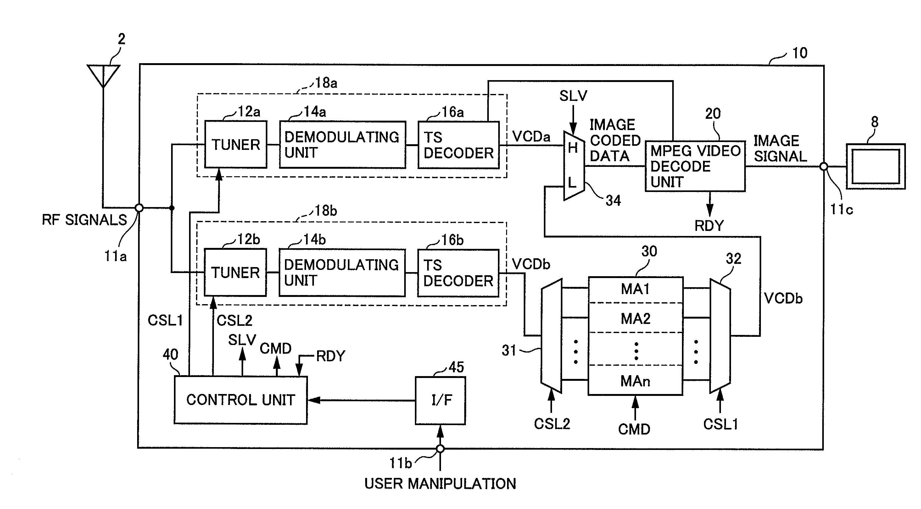
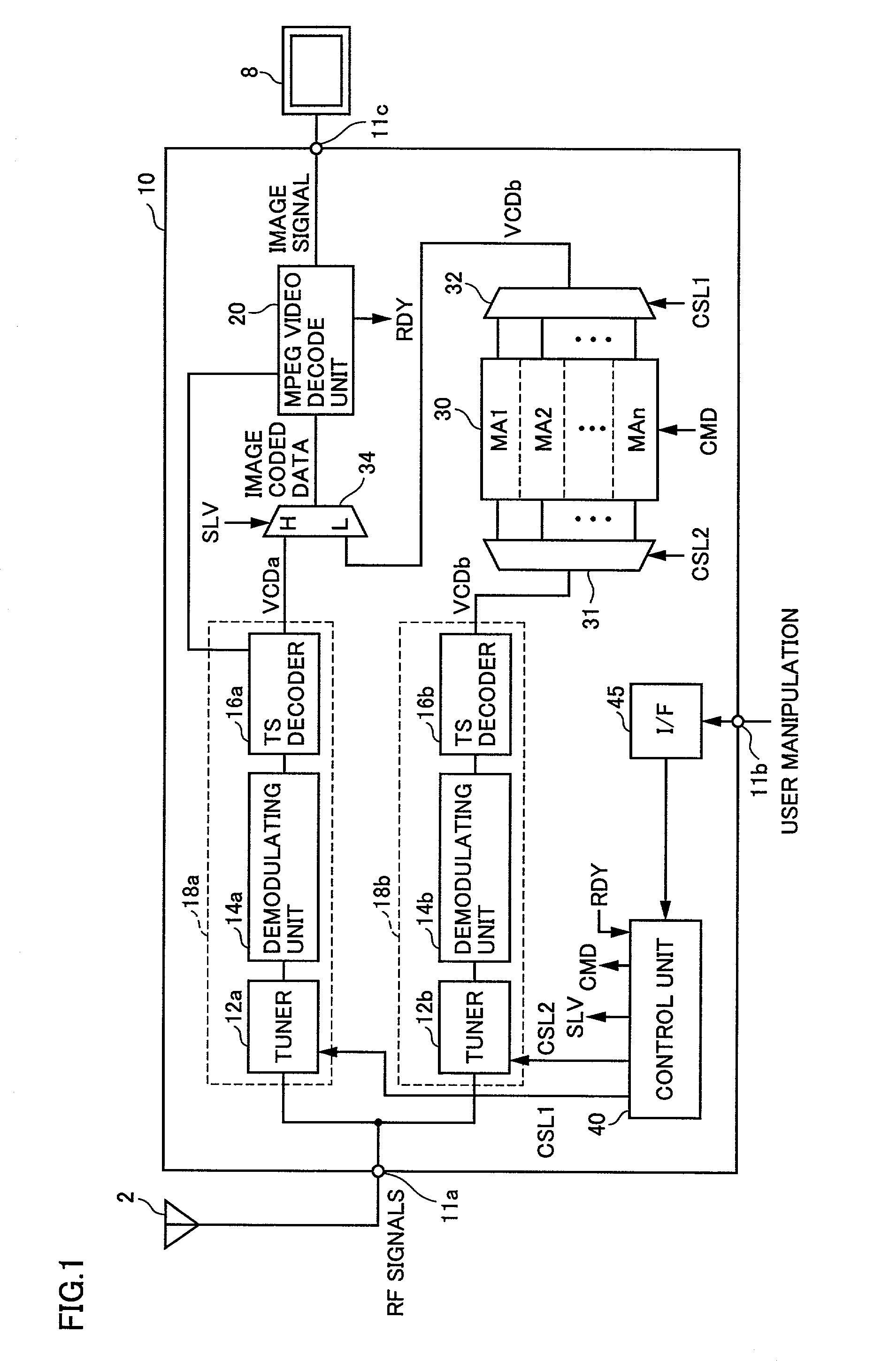
[0046]Referring to FIG. 1, a digital broadcast receiving apparatus 10 according to the first embodiment of the present invention includes an input terminal 11a for receiving RF signals which are the airwaves received by an antenna 2, an input terminal 11b for receiving user manipulation such as power-on and channel selection, and an output terminal 11c for outputting to an image display unit 8 an image signal corresponding to a desired channel selected by the user. The user manipulation that is input to input terminal 11b may be input from a user control unit integrally provided with digital broadcast receiving apparatus 10 by a panel or the like, or may be input using a remote control from outside digital broadcast receiving apparatus 10 by infrared rays or the like.

[0047]Digital broadcast receiving apparatus 10 further includes tuning units 18a and 18b for extracting the image coded data corresponding to a prescribed channel from the RF signals. Tuning unit 18a includes a tun...

second embodiment

[0083

[0084]Referring to FIG. 4, a digital broadcast receiving apparatus 50 according to the second embodiment of the present invention differs from digital broadcast receiving apparatus 10 shown in FIG. 1 in that it further includes an MPEG video decode unit 21 and an MPEG video encode unit 25 provided corresponding to background data.

[0085]MPEG video decode unit 21 first decodes image coded data VCDb output by tuning unit 18b in order to generate background data. MPEG video encode unit 25 recodes image coded data VCDb decoded by MPEG video decode unit 21 and outputs image coded data VCDb′. Memory unit 30 stores the recoded image coded data VCDb′ as the background data.

[0086]At this time, the recoding in MPEG video encode unit 25 is performed such that the amount of image coded data VCDb′ after recoding is smaller than the amount of image coded data VCDb as output from tuning unit 18b. For instance, the resolution upon recoding may be set lower than the resolution corresponding to n...

third embodiment

[0099

[0100]The first and second embodiments describe the arrangements in which the reproduction of background data of the respective channels that are periodically updated is performed when normal reproduction is impossible. In other words, the digital broadcast receiving apparatuses according to the first and second embodiments inevitably require a plurality of tuner systems (tuning units). The third embodiment describes an arrangement that allows picture display during the normal reproduction wait period in relation to the case where a single tuner system (tuning unit) is provided.

[0101]Referring to FIG. 6, a digital broadcast receiving apparatus 60 according to the third embodiment of the present invention includes an input terminal 11a for receiving RF signals which are the airwaves received by an antenna 2, an input terminal 11b for receiving user manipulation, an output terminal 11c for outputting to an image display unit 8 an image signal corresponding to a desired channel se...


PUM


Abstract

The digital broadcast receiving apparatus according to the present invention includes a tuning unit for outputting normal image data for performing a normal reproduction operation corresponding to a user selected channel, a memory unit for outputting background image data for performing a background reproduction operation when the normal reproduction operation cannot be performed, a data selector for receiving the normal image data and the background image data and outputting one of the normal image data and the background image data, and an MPEG video decode unit for decoding image data output by the data selector to generate an image signal. The tuning unit successively receives the respective channel selected in the background independently of the user selection, and stores the background image data corresponding to the respective channels in the memory unit.

Description

BACKGROUND OF THE INVENTION[0001]1. Field of the Invention[0002]The present invention relates to a digital broadcast receiving apparatus, and more specifically, to a digital broadcast receiving apparatus for receiving a digital television broadcast.[0003]2. Description of the Background Art[0004]In recent years, the digitization project of television broadcast is rapidly progressing worldwide. Particularly, in the field of digital television broadcast, the use of MPEG2 (Moving Picture Experts Group 2), which is an international standard of data compression / decompression, enables transmission of a plurality of channels with a single repeater so that the number of channels can be significantly increased. As a result, convenience for the user is expected to improve significantly.[0005]In receiving digital television broadcast, there is a need to decode compressed coded data to obtain the actual image signal and audio signal.[0006]FIG. 11 is a schematic block diagram representing an arr...

Claims


Application Information

Patent Timeline
Patent Type & Authority Patents(United States)
IPC IPC(8): H04N5/50H04N5/44H04N7/173H04N19/00H04N19/40H04N19/423H04N19/44H04N19/59
CPCH04N5/4401H04N21/4382H04N21/4383H04N21/433H04N21/44016H04N21/44209H04N21/4263H04N21/4435H04N21/426H04N5/445
Inventor OKADA, SHIGEYUKIYAMADA, KOUICHIMUKUNO, MAMORU
Owner SANYO ELECTRIC CO LTD
Why Eureka
Try Eureka