Method and apparatus for approximating depth of an object's placement onto a monitored region with applications to virtual interface devices

a virtual interface device and object placement technology, applied in static indicating devices, instruments, reradiation, etc., can solve the problems of difficulty in actually inputting messages using their small touch pads, and inability to accurately detect the depth of the placement of objects

Inactive Publication Date: 2006-05-23
HEILONGJIANG GOLDEN JUMPING GRP
View PDF40 Cites 172 Cited by
  • Summary
  • Abstract
  • Description
  • Claims
  • Application Information

AI Technical Summary

Benefits of technology

[0016]In one embodiment, a camera or other light detecting device can be positioned in or near the same plane with which an object's contact occurs. Because the camera can be positioned in this manner, the entire system can be packed into a small form-factor. For example, the entire system can be embedded into a single, very small package. In contrast, structured-light and triangulation systems require by their nature a camera that is well separated from the plane to be observed. Such systems cannot provide for simple small form-factor packaging.

Problems solved by technology

For example, although computers can now be implemented in almost pocket-size form factors, inputting data or commands on a mini-keyboard can be time consuming, awkward, and error prone.
While many cellular telephones today can handle e-mail communication, actually inputting messages using their small touch pads can be difficult.
A personal digital assistant (PDA) has much of the functionality of a computer but suffers from a tiny or non-existent keyboard.
This would lead to unpredictable backgrounds, and finger / background separation would be problematic.
Indeed objects such as a single hand may have in excess of 30 degrees of freedom, not even accounting for the deformation of the fingers as they strike the table.
Vann's method are therefore not applicable to hands and fingers.
Carau's system will not provide information from which relevant position can be uniquely determined without ambiguity.
Prior art attempts to use conventional two-dimensional cameras are known in the art, and suffer extremely acute occlusion problems in addition to ambiguity-creating problems.
Satisfactory operation of such systems requires that each stereo sensor be able to view all user fingers in the region of interest.
But in practice, one finger can very easily occlude the sensor-view of another user finger.
By definition, stereo cameras such as found in a Carau-type system, are spaced-apart along one axis (e.g., along the left-to-right width of a virtual keyboard), and as a result, finger occlusion is a very real and constant problem.
The occlusion problems would make a stereo system impractical for a virtual input device application.

Method used


Image

  • Method and apparatus for approximating depth of an object's placement onto a monitored region with applications to virtual interface devices
  • Method and apparatus for approximating depth of an object's placement onto a monitored region with applications to virtual interface devices
  • Method and apparatus for approximating depth of an object's placement onto a monitored region with applications to virtual interface devices

Examples


Embodiment Construction

[0033]Embodiments of the invention describe methods and apparatuses for approximating depth of an object's placement onto a monitored region with applications to virtual interface devices. In the following description, for the purposes of explanation, numerous specific details are set forth in order to provide a thorough understanding of the present invention. It will be apparent, however, that the present invention may be practiced without these specific details. In other instances, well-known structures and devices are shown in block diagram form in order to avoid unnecessarily obscuring the present invention.

[0034]A. Overview

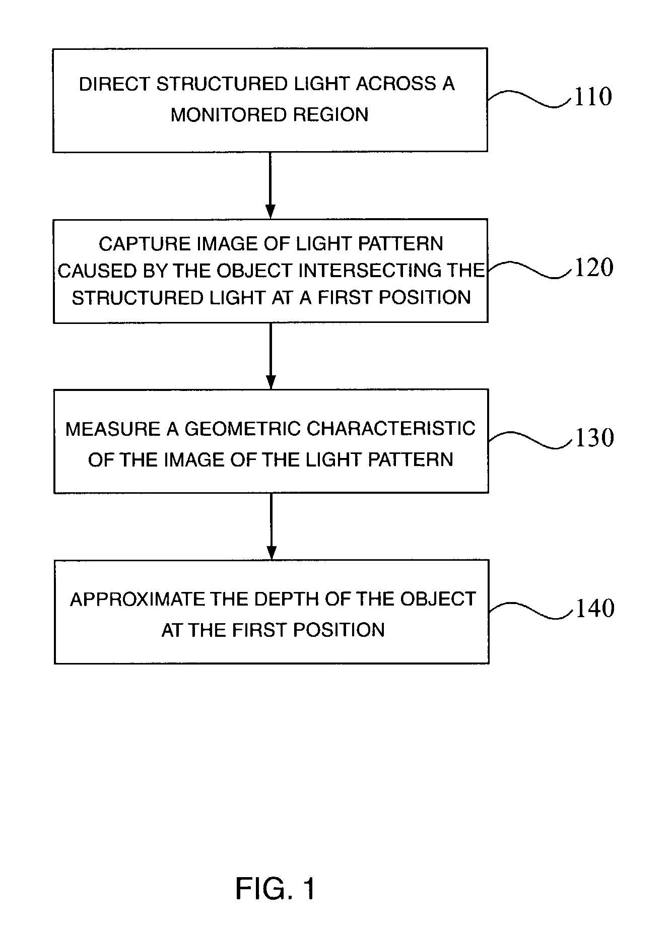
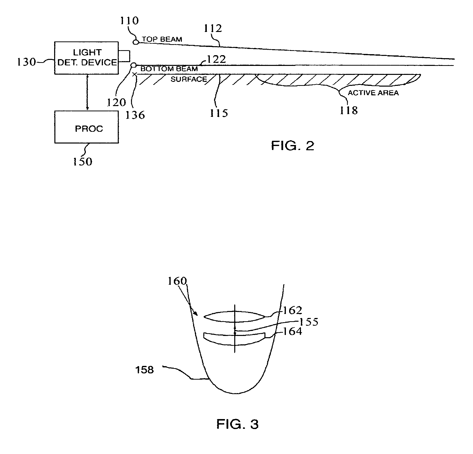
[0035]Embodiments of the invention encompass techniques for the determination of depth of an object that is placed onto a monitored region. The depth is determined relative to a position where the object is being viewed. Embodiments of the invention also include electronic devices that have components for performing such techniques.

[0036]An embodiment of the ...


PUM


Abstract

Structured light is directed across a monitored region. An image is captured of a light pattern that forms on the object as a result of the object intersecting the structured light when the object is placed at a first position in the monitored region. A geometric characteristic is identified of the image of the light pattern. The geometric characteristic is variable with a depth of the first position relative to where the image is captured. The depth of the first position is approximated based on the measured geometric characteristic.

Description

RELATED APPLICATION AND PRIORITY INFORMATION[0001]This application claims benefit of priority to Provisional U.S. Patent Application No. 60 / 382,899, entitled “Measurement Of Depth From Thickness Or Separation Of Structured Light With Application To Virtual Interface Devices,” filed May 22, 2002, the aforementioned priority application being hereby incorporated by reference in its entirety for all purposes.[0002]This application is related to U.S. application Ser. No. 10 / 246,123, filed on Sep. 17, 2002, entitled “Method And Apparatus For Approximating Depth Of An Object's Placement Onto A Monitored Region With Applications To Virtual Interface Devices”, by Carlo Tomasi and Salih Burak Gokturk.FIELD OF THE INVENTION[0003]The present invention relates to position detection methods and apparatuses. In particular, the present invention relates to a method and apparatus for approximating depth of an object's placement onto a monitored region with applications to virtual interface devices....

Claims


Application Information

Patent Timeline
Patent Type & Authority Patents(United States)
IPC IPC(8): G01B11/24G09G5/00G01S17/06G06F1/16G06F3/038G06F3/042
CPCG06F1/1626G06F1/1632G06F1/1673G06F3/0426G06F3/0428G06F3/04886G06F3/038G01S17/06G06F2200/1633
Inventor TOMASI, CARLOGOKTURK, SALIH BURAK
Owner HEILONGJIANG GOLDEN JUMPING GRP
Why Eureka
Try Eureka