Optical recording medium recorded with information in depth direction, and method and apparatus of reproduction therefrom

Inactive Publication Date: 2006-05-23
SHARP KK
View PDF27 Cites 20 Cited by
  • Summary
  • Abstract
  • Description
  • Claims
  • Application Information

AI Technical Summary

Benefits of technology

[0037]An object of the present invention is to provide an optical recording medium and a reproduction method and apparatus thereof that allows

Problems solved by technology

There was a problem that the region where user data can be recorded on the disk is reduced.
There was a problem that the region where the user can write data on the disk is reduced.

Method used


Image

  • Optical recording medium recorded with information in depth direction, and method and apparatus of reproduction therefrom
  • Optical recording medium recorded with information in depth direction, and method and apparatus of reproduction therefrom
  • Optical recording medium recorded with information in depth direction, and method and apparatus of reproduction therefrom

Examples


Example

[0084]First Embodiment

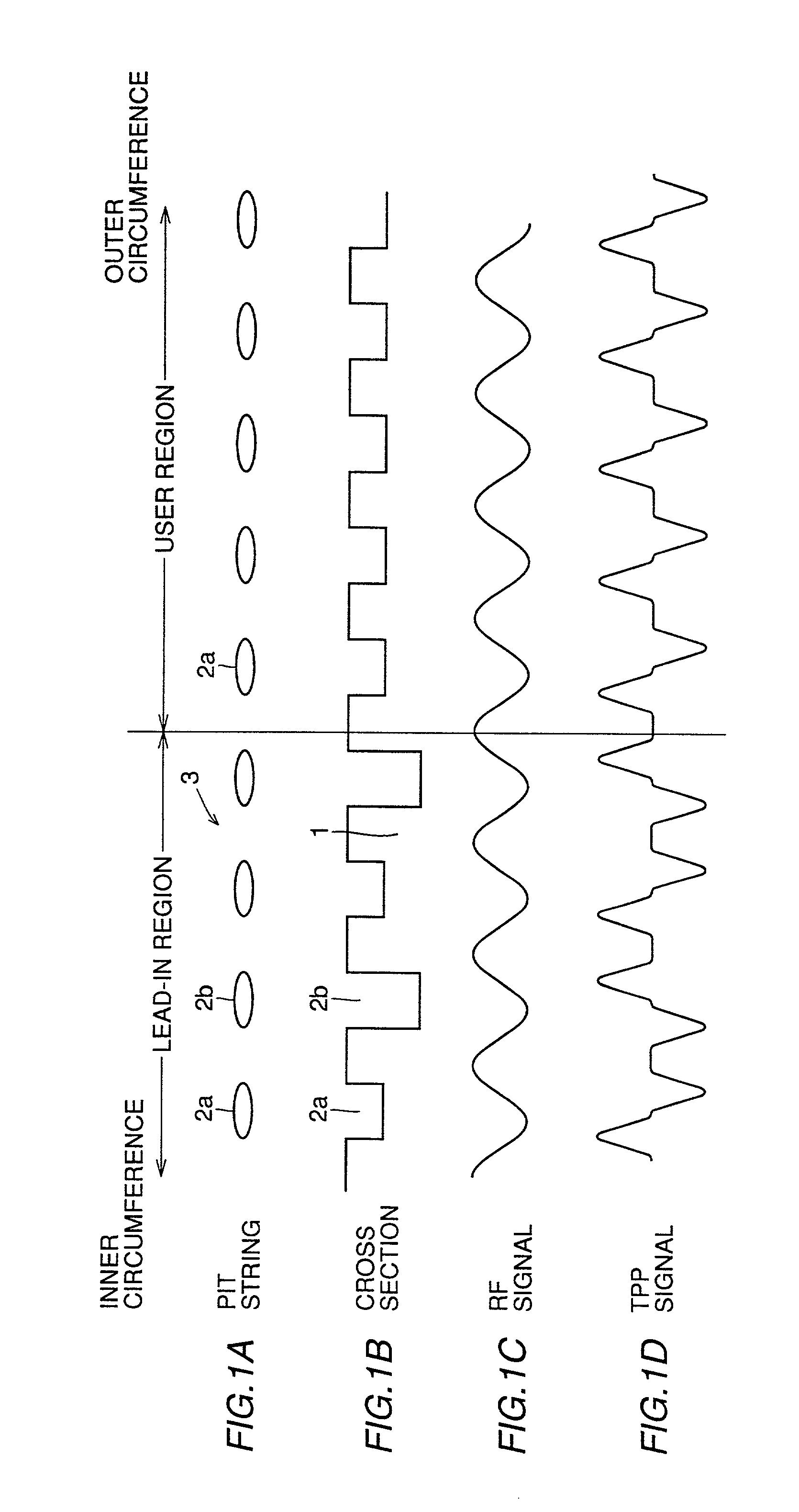
[0085]An optical recording medium and a reproduction method and apparatus thereof according to a first embodiment of the present invention will be described hereinafter. FIGS. 1A and 1B schematically show a structure of a pit string on a ROM disk as an example of an optical recording medium in the first embodiment. FIGS. 1C and 1D represent the waveforms of signals obtained by reproducing information from the ROM disk.

[0086]More specifically, FIG. 1A schematically shows pit string 3 constituted by two types of pits 2a and 2b, illustrated in a linear version from the inner circumference region to the outer circumference region of the disk. FIG. 1B schematically shows the cross section of the disk, corresponding to pit string 3 of FIG. 1A. Referring to FIG. 1B, the lead-in region is formed of relatively shallow pits 2a (depth D1) and relatively deep pits 2b (depth D2). The user region is formed of pits 2a of a constant depth (depth D1). FIG. 1C shows an RF signal...

Example

[0105]Second Embodiment

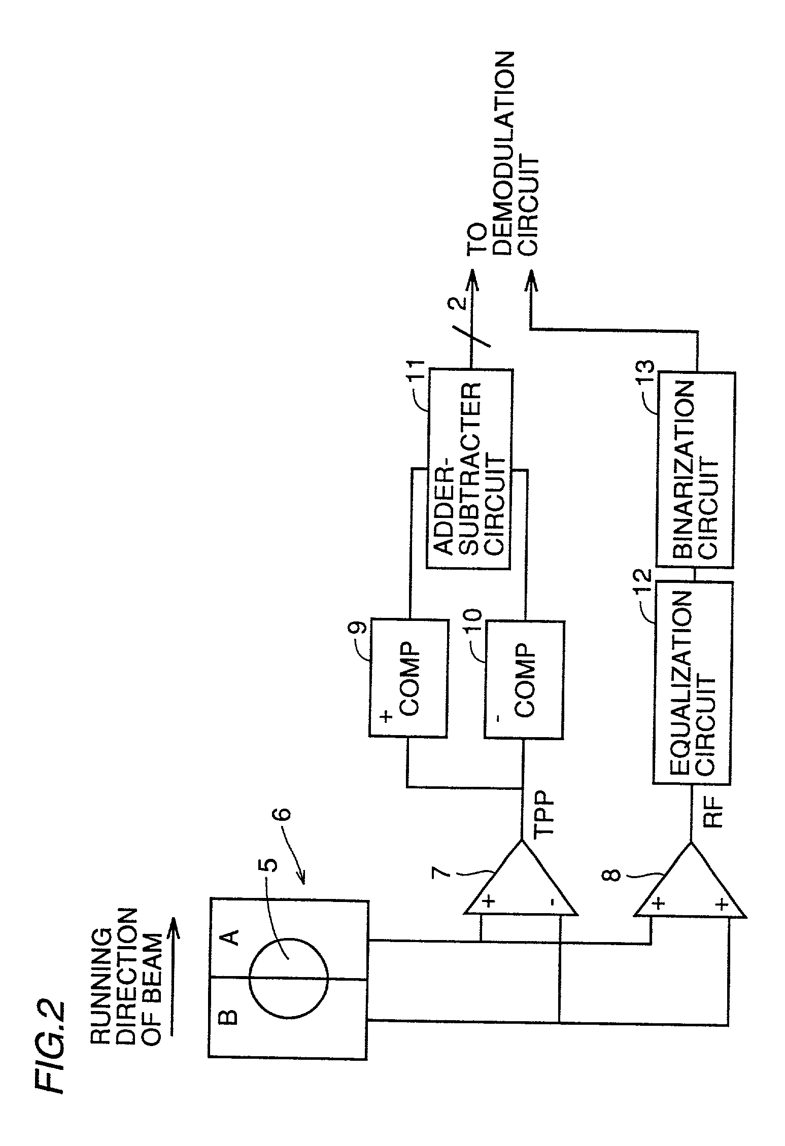
[0106]Referring to FIG. 4, an identify circuit of recorded information in a reproduction apparatus of an optical recording medium according to a second embodiment of the present invention will be described with reference to FIG. 4. More particularly, FIG. 4 is a block diagram showing the circuit configuration that allows detection of the presence of pits from which a TPP signal of different polarity can be obtained on the optical disk.

[0107]Similar to the reproduction apparatus of the first embodiment shown in FIG. 2, the outputs from regions A and B of detector 6 are provided to differential amplifier 7 and addition amplifier 8. Similar to the first embodiment of FIG. 2, the TPP signal which is the output of differential amplifier 7 is applied to comparators 9 and 10. The TPP signals binarized by respective comparators 9 and 10 are applied to a marker detection circuit 15. The RF signal which is the output of addition amplifier 8 is provided to comparator 14 ...

Example

[0110]Third Embodiment

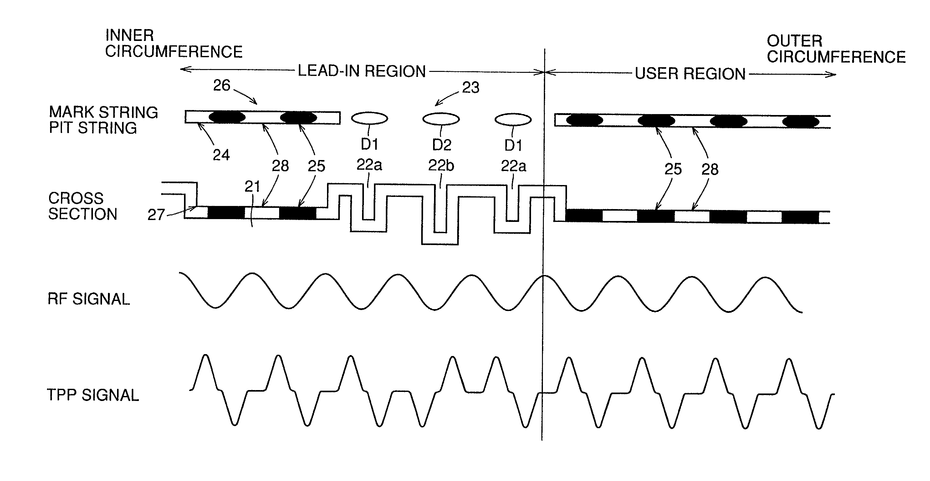
[0111]A recordable disk as an example of an optical recording medium according to a third embodiment of the present invention will be described here with reference to FIGS. 5A–5D. FIGS. 5A and 5B schematically show the structure of a mark string and pit string on a recordable disk according to the third embodiment. FIGS. 5C and 5D represent the waveforms of signals obtained by reproducing the information recorded on the disk.

[0112]In general, mark 25 is written in either or both of the groove and land. The third embodiment of FIG. 5 corresponds to the example where marks 25 are written in groove 24.

[0113]More specifically, FIG. 5A schematically shows mark strings 26 constituted by marks 25 formed in groove 24 and a pit string 23 constituted by pits 22a and 22b arranged between these mark strings, illustrated in a linear version from the inner circumference region to the outer circumference region of the disk. FIG. 5B schematically shows the cross section of the...


PUM


Abstract

An optical disk has a lead-in region provided at the inner circumference side and a user region provided at the outer circumference side. Pit string 3 of pits of different depths is formed in the lead-in region. Light beam reflected from the pit string is detected by detector and TPP and RF signals are output by differential amplifier and addition amplifier. A ternary signal is restored from pits based on the TPP and RF signals. Information is recorded by pits of the same depth in the user region. Recording information in the depth direction in the lead-in region increases the recording capacity thereof. The information recorded in the depth direction in the lead-in region cannot be transferred to a user region of another optical disk.

Description

BACKGROUND OF THE INVENTION[0001]1. Field of the Invention[0002]The present invention relates to an optical recording medium in which information is recorded in the direction of depth of the substrate, and a method and apparatus of reproducing information therefrom. More particularly, the present invention relates to a read only or recordable optical recording medium including a first region in which first information such as additional information is recorded at least in the depth direction of the substrate and a second region in which second information such as main information is recorded or can be recorded in the plane direction of the substrate, and a reproduction method and reproduction apparatus of such an optical recording medium.[0003]2. Description of the Background Art[0004]In a conventional optical recording medium such as an optical disk, binary recording is carried out, wherein information is binarized and recorded corresponding to the presence / absence, the length, the...

Claims


Application Information

Patent Timeline
IPC IPC(8): G11B7/00G11B7/005G11B7/007G11B7/013G11B7/24035G11B7/24047G11B7/24079G11B7/24085G11B20/00
CPCG11B7/005G11B7/007G11B20/00688G11B20/00086G11B7/24085
Inventor NAKAJIMA, JUNSAKUTAKEUCHI, HITOSHINOMURA, MASARUOHTA, KENJI
Owner SHARP KK
Why Eureka
Try Eureka