
Radiographic apparatus, radiographic method, program, computer-readable storage medium, radiographic system, image diagnosis aiding method, and image diagnosis aiding system

a radiographic method and radiographic apparatus technology, applied in the field of radiographic apparatus, radiographic method, radiographic system, image diagnosis aiding method, image diagnosis aiding system, can solve the problem of increasing the amount of delay, affecting the patient's health, and difficult to achieve appropriate exposure timing

Inactive Publication Date: 2006-05-23
CANON KK
View PDF7 Cites 53 Cited by
  • Summary
  • Abstract
  • Description
  • Claims
  • Application Information

AI Technical Summary

Benefits of technology

[0002]The present invention relates to a radiographic apparatus, a radiographic method, a program, a computer-readable storage medium, a radiographic system, an image diagnosis aiding method, and an image diagnosis aiding system.

Problems solved by technology

This is because it is more difficult to achieve appropriate timing of exposure, using machine guidance.
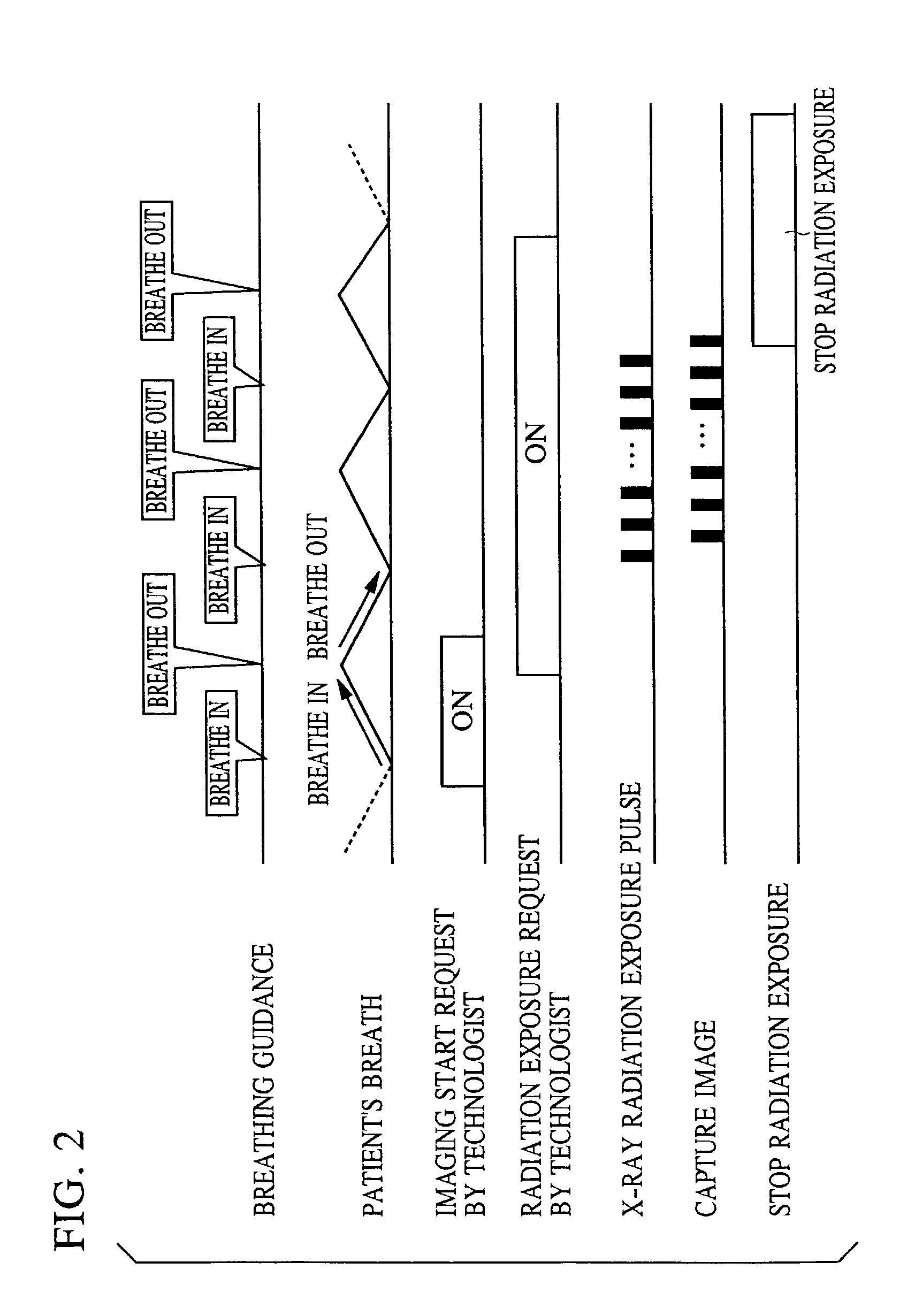
In imaging of the lung during breathing, as opposed to still imaging of the lung with the breath held, it is difficult to acquire image data of a breathing cycle (breathing period) accurately in phase (e.g., to acquire image data from start of inhaling to end of exhaling) within dynamic images that are continuously captured.
This is because even if a patient is instructed to start inhaling upon start of imaging, some amount of delay—an amount that depends on the patient—occurs.
In particular, the delay is prominent in aged patients or patients with weakened physical strength since these patients are unable to respond quickly.
When a doctor diagnoses images that have been thus taken, if the phase of breathing at start of image display differs from patient to patient, a diagnosis method cannot be fixed and diagnosis will take more time.
However, this requires an instrument to be attached to a patient, which adds labor and time to the procedure.
Furthermore, when imaging is performed over a breathing cycle, including inhaling and exhaling, during approximately ten seconds, it is difficult for a technologist suitably to control an inhaling phase and an exhaling phase to be five seconds each while monitoring the patient.

Method used


Image

  • Radiographic apparatus, radiographic method, program, computer-readable storage medium, radiographic system, image diagnosis aiding method, and image diagnosis aiding system
  • Radiographic apparatus, radiographic method, program, computer-readable storage medium, radiographic system, image diagnosis aiding method, and image diagnosis aiding system
  • Radiographic apparatus, radiographic method, program, computer-readable storage medium, radiographic system, image diagnosis aiding method, and image diagnosis aiding system

Examples


first embodiment

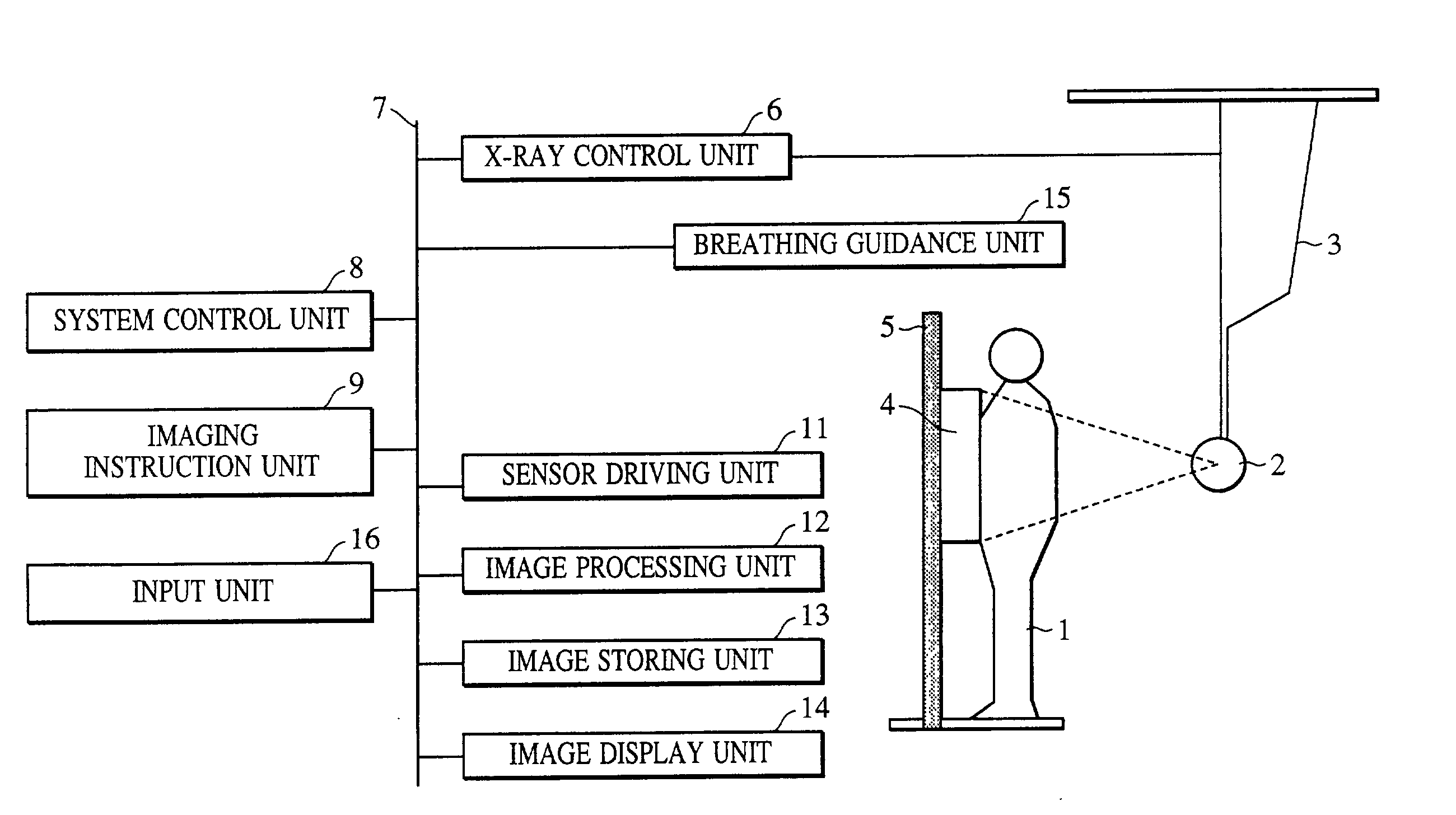
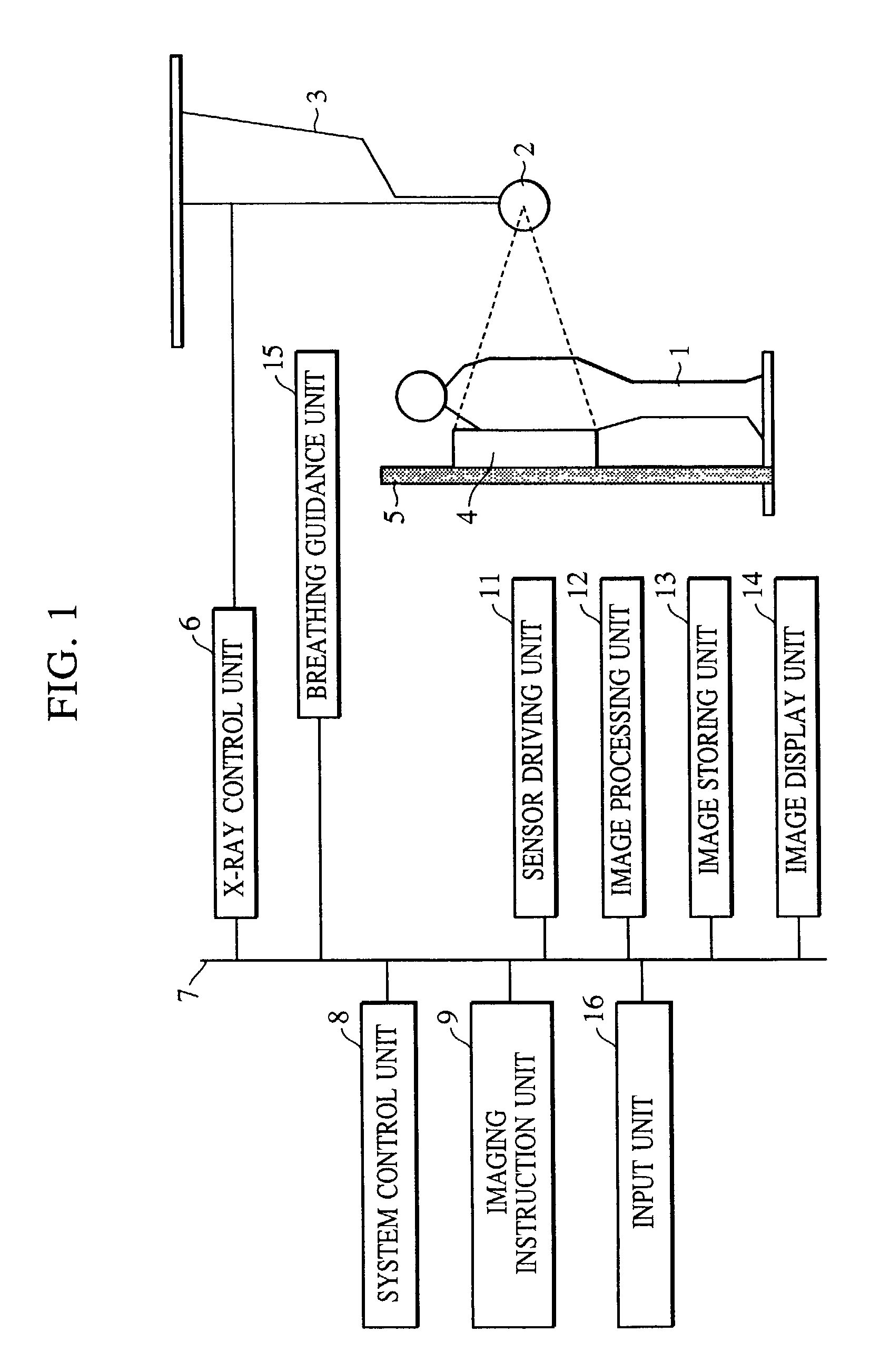
[0026]FIG. 1 shows the construction of a system according to a first embodiment of the present invention. Referring to FIG. 1, a two-dimensional sensor 4, constituting an imaging unit, includes an amorphous semiconductor and a fluorescent screen, and it has 2,688×2,688 pixels each with a size of 160 μm×160 μm. The sensor 4 is attached to a stand 5 and is used for imaging an object in an upright position.

[0027]An X-ray tube 2 is suspended from a ceiling by a ceiling suspension unit 3 so as to be movable in accordance with the body of a patient (also referred to as a human body). X-rays produced by the X-ray tube 2 are transmitted through the patient to reach the sensor 4. The X-rays are converted into visible light by the fluorescent screen, and the visible light is converted into image data by the amorphous semiconductor. Timing of imaging is controlled based on instruction(s) entered from an imaging instruction unit 9 by a radiographic technologist (operator) or the like. Based on ...

second embodiment

[0041]Although the first embodiment has been described in the context of dynamic imaging of respiration, dynamic imaging is also effective for diagnosis of other body parts capable of motion, such as the abdomen (in abdominal respiration), the lumbar vertebrae and the extremities and the like including joints in bending and stretching motion, and the like. In dynamic imaging for these body parts, guiding of the dynamic state (moving state) of the relevant body part is also needed, since diagnosis will be difficult if the dynamic state (cycle, changing process of phase, or the like, of the dynamic state) of the body part is left up to each patient. As an example, FIG. 4 shows dynamic images of a knee joint during a bending and stretching motion. FIG. 4 shows some of twenty frames acquired by dynamic imaging of the knee joint. The knee joint is initially stretched in a state F0, and is gradually bent until reaching a state F10 or F11. Then, conversely, the knee joint is gradually stre...


PUM


Abstract

A radiographic apparatus or system for imaging a dynamic state or process of an object such as a human body includes an indication unit for performing dynamic state guiding indication using a perceivable pattern corresponding to a dynamic state or motion to be engaged in by the patient, and an image acquisition unit for acquiring a plurality of radiographs of the human body. The resulting radiographs can be reviewed for diagnosis, and can be stored, either locally or at a remote location.

Description

BACKGROUND OF THE INVENTION[0001]1. Field of the Invention[0002]The present invention relates to a radiographic apparatus, a radiographic method, a program, a computer-readable storage medium, a radiographic system, an image diagnosis aiding method, and an image diagnosis aiding system.[0003]2. Description of the Related Art[0004]In recent years, systems that employ large-area semiconductor image sensors to radiograph an object have been developed. Such a system has practical advantages, as compared with a conventional radiographic system based on silver salt films, in that an image can be recorded over an extremely large range of radiation dose. More specifically, X-rays with an extremely wide dynamic range are read as electric signals using a photoelectric converter, and the electric signals are converted into digital signals. The digital signals are processed to output a high-quality radiograph as a visible image on a recording material such as a photosensitive film material, or ...

Claims


Application Information

Patent Timeline
IPC IPC(8): H05G1/10A61B6/00A61B5/00A61B6/02G03B42/02
CPCA61B6/5217A61B6/02G16H50/30A61B6/4429
Inventor TSUJII, OSAMU
Owner CANON KK
Learn More