
Optical fiber holder and optical fiber holding method

a technology of optical fiber and optical fiber, which is applied in the direction of optical light guides, bundled fibre light guides, instruments, etc., to achieve the effects of enhancing light transmissivity, reliably holding, and convenient and reliable us

Inactive Publication Date: 2006-05-23
CCS INC
View PDF18 Cites 1 Cited by
  • Summary
  • Abstract
  • Description
  • Claims
  • Application Information

AI Technical Summary

Benefits of technology

[0008]The optical fiber holder thus constructed does not use adhesive and hence does not allow capillarity to occur in clearances defined between optical fibers as does the prior art. Thus, the optical fiber holder does not impair the flexibility of the optical fiber bundle and hence can be suitably applied to various use conditions. Further, the optical fiber holder is capable of holding plural optical fibers in a bundled state easily and properly by means of the pressing structure. In fusing the leading edge of the optical fiber bundle inserted through the tubular member for the purpose of end face treatment by applying heat and pressure thereto with a hot plate or the like, the optical fiber bundle is likely to escape rearwardly if it is held by the prior art device. The pressing structure employed in the optical fiber holder of the present invention is capable of effectively preventing the optical fiber bundle from escaping rearwardly, thereby allowing the end face treatment of the leading edge of the optical fiber bundle to be achieved easily and assuredly. Thus, the optical fiber holder is convenient for the end face treatment to be achieved.
[0015]In accordance with still another aspect of the present invention, there is provided a method of holding an optical fiber bundle with adhesive, comprising the steps of inserting the optical fiber bundle comprising a bundle of plural optical fibers through a tubular member having an aperture extending through a peripheral wall thereof from an outer periphery to an inner periphery of the tubular member; injecting a predetermined amount of adhesive into the optical fiber bundle through the aperture to fix and hold the optical fibers relatively tightly. This method is capable of eliminating the time and labor which would otherwise be required to apply adhesive to the optical fibers one by one as well as of properly holding the optical fiber bundle by bonding and fixing the optical fibers to each other and to the tubular member following a very simple procedure. Further, since adhesive is injected into the optical fiber bundle having been bundled beforehand, it is possible to minimize the amount of adhesive to be used, which makes it possible to reduce the region permitting capillarity to occur therein to a minimum. As a result, the portion of the optical fiber bundle extending outwardly of the optical fiber holder can assuredly have sufficient flexibility.

Problems solved by technology

The optical fiber holder thus constructed does not use adhesive and hence does not allow capillarity to occur in clearances defined between optical fibers as does the prior art.

Method used


Image

  • Optical fiber holder and optical fiber holding method
  • Optical fiber holder and optical fiber holding method
  • Optical fiber holder and optical fiber holding method

Examples


Embodiment Construction

[0025]The present invention will now be described in detail with reference to the drawings.

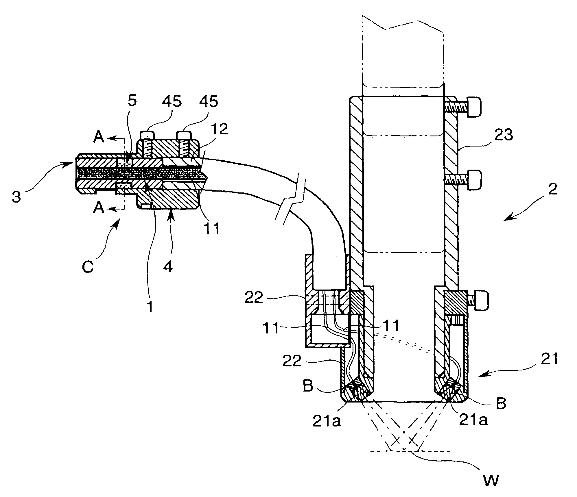
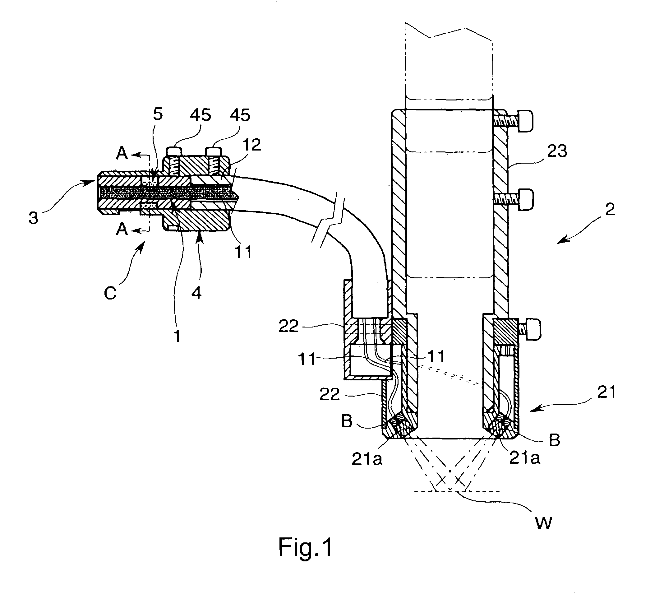
[0026]Referring first to FIG. 1 showing an optical fiber holder C according to one embodiment of the present invention, the optical fiber holder C, which functions, for example, as a connector for holding one end portion of an optical fiber bundle 1, is connected to a head 2.

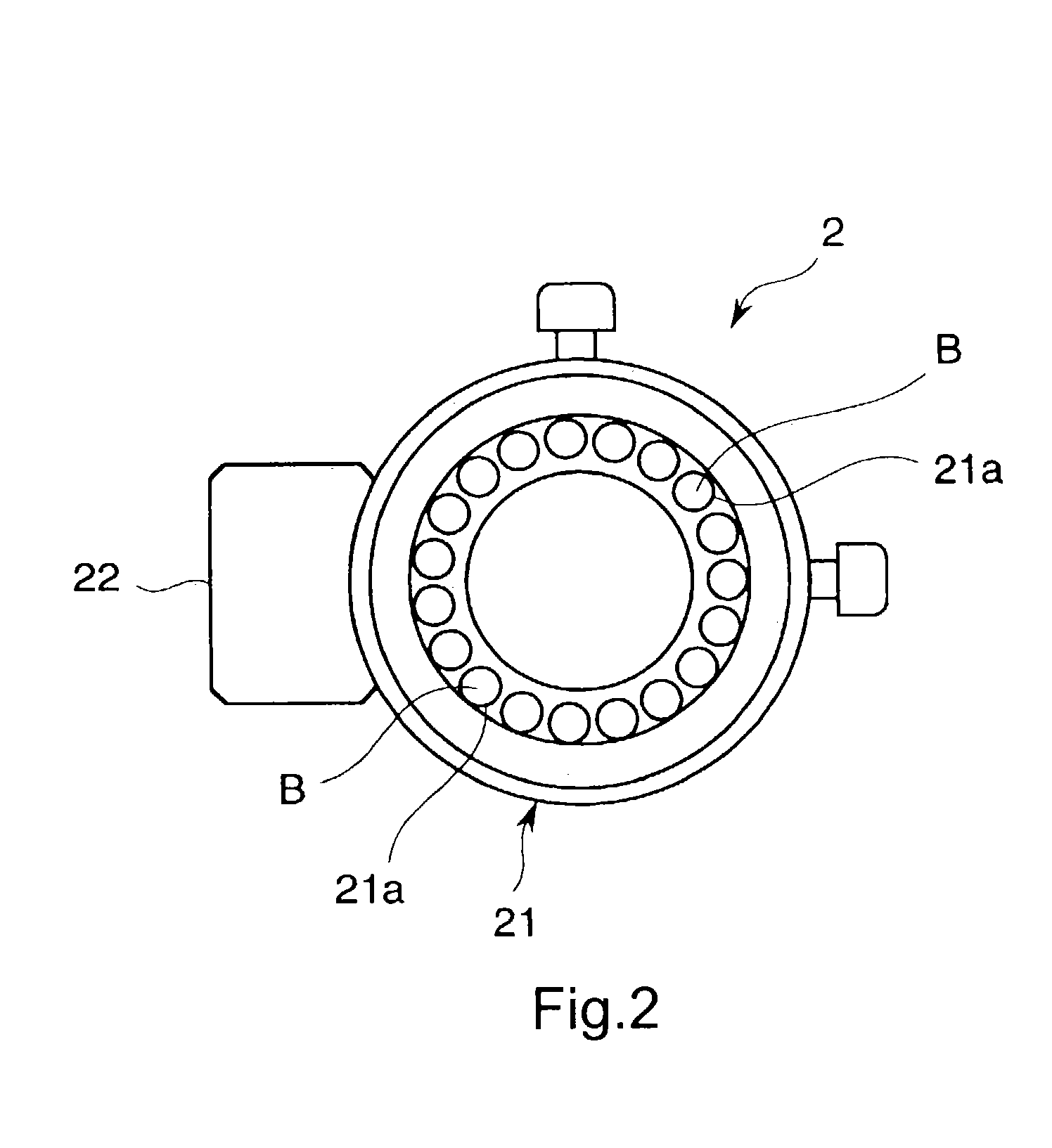
[0027]The head 2 includes an annular bead body 21, a cover 22 fitting over the head body 21, and a fitting portion 23 capable of adjusting the distance between the head body 21 and a work W to be illuminated, as shown in FIGS. 1 and 2.

[0028]The head body 21 is adapted to hold the light-emitting end portions of respective optical fibers 11 as equispaced along the circumference thereof as well as ball lenses B as facing respective light-emitting ends of the optical fibers 11, the optical fibers 11 being branched from the other end of the optical fiber bundle 1. The head body 21 serves to direct light rays emitted from the op...


PUM


Abstract

An improved optical fiber holder is provided, including: a tubular member (3) for fitting over an optical fiber bundle (1) consisting of a bundle of plural optical fibers (11) to prevent the optical fibers (11) from separating from each other; and a pressing structure (5) for exerting a pressing force on the optical fiber bundle (1) in a direction perpendicular to a longitudinal direction of the optical fiber bundle (1) to press the optical fiber bundle (1) against an inner periphery (3a) of the tubular member (3).

Description

BACKGROUND OF THE INVENTION[0001]1. Field of the Invention[0002]The present invention relates to a device and method for holding a plurality of optical fibers in a bundled state.[0003]2. Description of the Related Art[0004]One prior art device for holding a bundle of plural optical fibers has a bore extending through a member such as a connector for holding a bundle of optical fibers bonded and fixed to each other with adhesive applied to a portion of each optical fiber to be bonded to other optical fibers by allowing the bundle to be inserted therethrough.[0005]With such a device, adhesive must be applied to optical fibers one by one and, hence, the operation of forming a single optical fiber bundle is very troublesome and inconvenient. The use of adhesive enables adjacent optical fibers to be fixed to each other relatively tightly in a certain region by virtue of capillarity occurring in clearances defined between optical fibers. The prior art device, however, requires that adhesi...

Claims


Application Information

Patent Timeline
Patent Type & Authority Patents(United States)
IPC IPC(8): G02B6/00G02B6/36G02B6/04G02B6/40
CPCG02B6/403
Inventor YONEDA, KENJI
Owner CCS INC
Learn More