Hardware accelerated compression

a compression algorithm and hardware acceleration technology, applied in the field of http compression, can solve the problems that data compression algorithms can be generally characterized as lossless or lossy, and achieve the effect of enhancing overall data throughput and increasing compression speed

Active Publication Date: 2006-05-23
F5 NETWORKS INC
View PDF4 Cites 190 Cited by
  • Summary
  • Abstract
  • Description
  • Claims
  • Application Information

AI Technical Summary

Benefits of technology

[0010]Briefly stated, an apparatus, system, and method is related to a compression system that is arranged to use software and / or hardware accelerated compression techniques to increase compression speeds and enhance overall data throughput. A logic circuit is arranged to: receive a data stream from a flow control processor, buffer the data stream, select a compression ASIC, and forward the data to the selected ASIC. Each ASIC performs compression on the data (e.g., LZ77), and sends the compressed data back to the logic circuit. The logic circuit receives the compressed data, converts the data to another compressed format (e.g., GZIP), and forwards the converted and compressed data back to the flow control processor. History associated with the data stream can be stored in memory by the flow control processor, or in the logic circuit.

Problems solved by technology

Data compression algorithms can be generally characterized as lossless or lossy.

Method used


Image

  • Hardware accelerated compression
  • Hardware accelerated compression
  • Hardware accelerated compression

Examples


example process

Flow

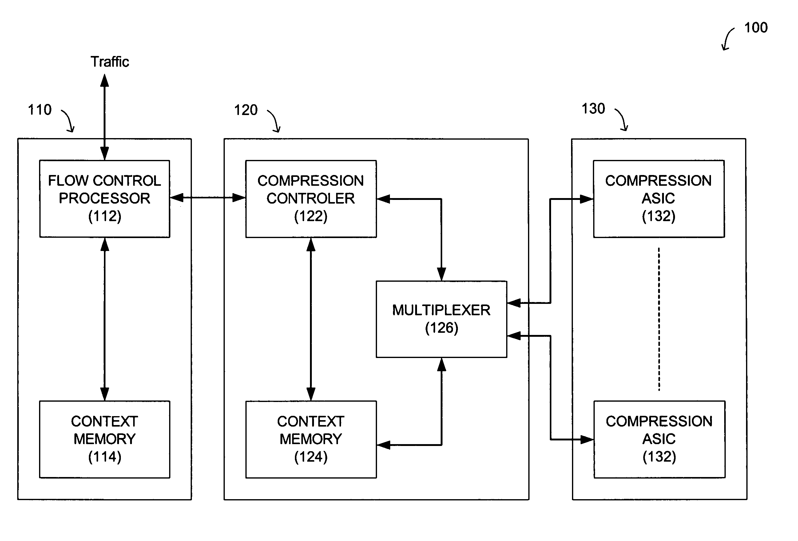
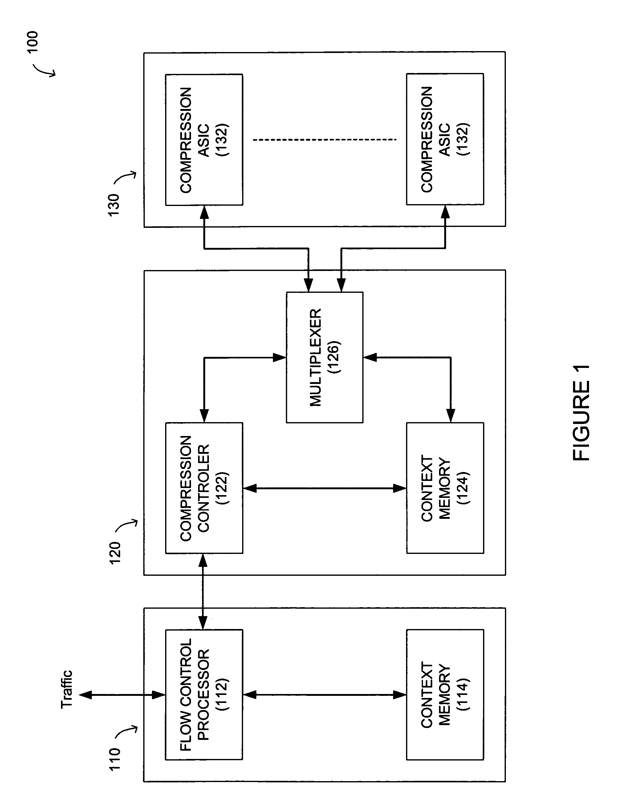
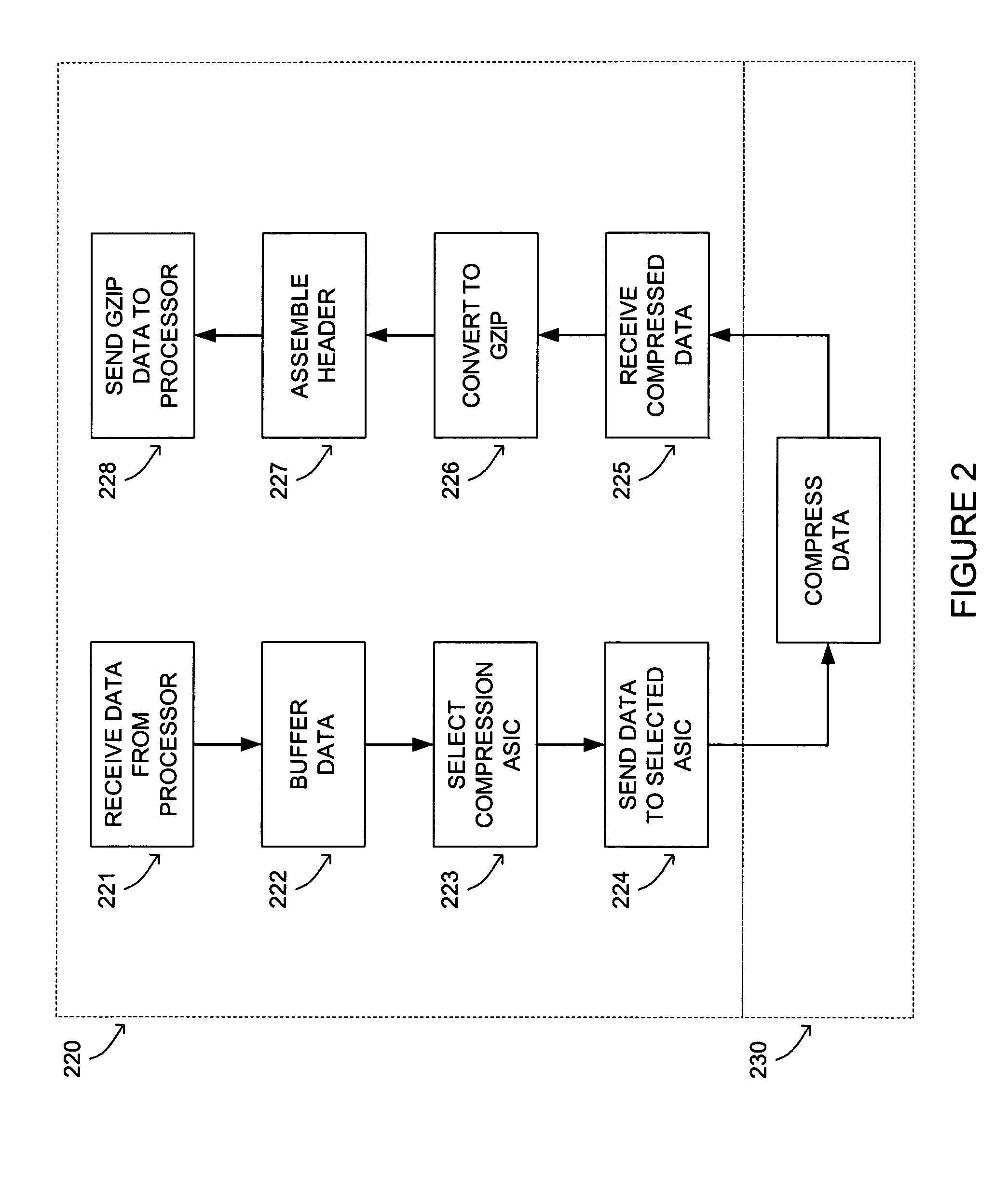
[0028]FIG. 2 is an illustration of a process for example system 100 that is arranged according to an example embodiment of the present invention. Processing for an example logic block (120) is illustrated by processing steps 220, while processing step 230 illustrates processing for an example compression ASIC (132).

[0029]Initially, the flow controller (110) receives ingress traffic. A data stream associated with a flow is sent to the logic block (120) by the flow control processor (112). The compression controller (122) receives the data stream from the flow control processor (112) at block 221, and stores the data stream in memory (124) at block 222. At block 223, the compression controller (122) selects a compression ASIC (e.g., with multiplexer 126). The buffered data stream is sent to the selected compression ASIC (132) at block 224. At block 230, each compression ASIC (132) operates on a respective data stream to provide compressed data such as LZ77 compression. The compres...


PUM


Abstract

A compression system is arranged to use software and/or hardware accelerated compression techniques to increase compression speeds and enhance overall data throughput. A logic circuit is arranged to: receive a data stream from a flow control processor, buffer the data stream, select a hardware compressor (e.g., an ASIC), and forward the data to the selected hardware compressor. Each hardware compressor performs compression on the data (e.g., LZ77), and sends the compressed data back to the logic circuit. The logic circuit receives the compressed data, converts the data to another compressed format (e.g., GZIP), and forwards the converted and compressed data back to the flow control processor. History associated with the data stream can be stored in memory by the flow control processor, or in the logic circuit.

Description

FIELD OF THE INVENTION[0001]The present invention is related to HTTP compression. More particularly, the present invention is related to a compression system that utilizes software and / or hardware accelerated compression techniques to increase compression speeds and overall data throughput.BACKGROUND OF THE INVENTION[0002]Data compression is used in a variety of programming contexts to provide increased speeds in data transfers. Typical compression algorithms review the entire data set and attempt to remove redundancy from the data set. Redundancy can take the form of repeated bit sequences, repeated byte sequences, as well as other forms of repeated sequences.[0003]Data compression algorithms can be generally characterized as lossless or lossy. Lossless compression involves the transformation of a data set such that an exact reproduction of the data set can be retrieved by applying a decompression transformation. Lossless compression is most often used to compact data, where an exa...

Claims


Application Information

Patent Timeline
Patent Type & Authority Patents(United States)
IPC IPC(8): G06F13/12
CPCH03M7/3084G06F13/122
Inventor FRANKLIN, JASON G.
Owner F5 NETWORKS INC
Why Eureka
Try Eureka