Mechanical locking system for floating floor

a technology of mechanical locking and floating floor, which is applied in the field of floorboards, can solve the problems of incomplete floor panels, considerable waste of materials, and relatively expensive techniques used to manufacture such floorboards with mechanical locking systems, and achieve the effect of rationality and cost-effectiveness

Inactive Publication Date: 2006-05-30
VÄLINGE INNOVATION AB
View PDF387 Cites 315 Cited by
  • Summary
  • Abstract
  • Description
  • Claims
  • Application Information

AI Technical Summary

Benefits of technology

[0048]An object of the present invention is to eliminate or significantly reduce one or more of the problems occurring in connection with manufacture of floorboards with mechanical locking systems. This is applicable in particular to such floorboards with mechanical locking systems as are made in one piece with the core of the floorboard. A further object of the invention is to provide a rational and cost-efficient manufacturing method for manufacturing elements which are later to constitute parts of the mechanical locking system of the floorboards. A third object is to provide a rational method for joining of these elements with the joint portion of the floorboard to form an integrated mechanical locking system which locks vertically and horizontally.

Problems solved by technology

The above methods can, in some cases, result in completed floor panels.
The techniques used to manufacture such floorboards with mechanical locking systems, however, are still relatively expensive since the machining of the joint portions for the purpose of forming the mechanical locking system causes considerable amounts of wasted material, in particular when the width of the floorboards is reduced so that the length of the joint portions per square meter of floor surface increases.
6. As shown in these figures, the mechanical locking systems have parts which project past the upper joint edges and this causes expensive waste (w), owing to the removing of material performed by the sawblade SB when dividing the floor element and when surface material is removed and the core is machined in connection with the forming of the parts of the locking syst
These systems and the manufacturing methods suffer from a number of drawbacks which are above all related to cost and function.
For example, the aluminum oxide and also the reinforcing layers which give the laminate floor its high wearing strength and impact resistance causes great wear on the tools, such as the diamond teeth.
Frequent and expensive regrinding is made particularly of the tool parts that remove the surface layer.
Also, machining of the joint edges causes expensive waste when core material and surface material are removed to form the parts of the locking system.
This may result in production problems and considerable investments especially when manufacturing parquet flooring.
In addition, a mechanical locking system has a more complicated geometry than a locking system which is joined by gluing.
Such quality requirements, which are used for the locking system, are not always used for the other properties of the floor, such as stability and impact strength.
Owing to the locking system, the core of the entire floorboard is of unnecessarily high quality, which increases the manufacturing cost.
This usually causes poorer strength and difficulties in laying or detaching the floorboards.
These methods may result in great strength and good function but are generally more expensive.
In some cases, these methods may result in a somewhat lower cost than a machined embodiment, but this implies that floorboards are expensive to manufacture and that the waste is very costly, as may be the case when the floorboards are made of, for example, high quality high pressure laminate.
In less expensive floorboards of low pressure laminate, the cost of these locking systems of metal is higher than in the case where the locking system is machined from the core of the board.
Gluing is difficult and machining is not simple.
This results in laborious laying and the manufacturing costs is high.
They are not convenient for use in thin flooring.
All these alternatives have a poor function and are more expensive to manufacture and use than known machined locking systems.
This is an expensive and complicated method.
It is also possible to form strips as sections by extrusion of plastic or metal, for instance aluminum, but this may be more expensive than machining.

Method used


Image

  • Mechanical locking system for floating floor
  • Mechanical locking system for floating floor
  • Mechanical locking system for floating floor

Examples


Embodiment Construction

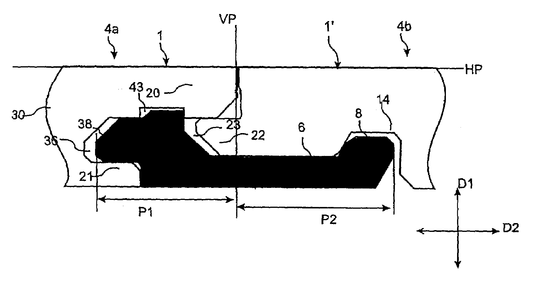
[0097]A first preferred embodiment of a floorboard 1, 1′ provided with a mechanical locking system according to the invention will now be described with reference to the embodiments shown in FIGS. 9a–d. To facilitate understanding, the locking system is shown schematically. It should be emphasized that an improved function can be achieved using other preferred embodiments that will be described below.

[0098]FIG. 9a illustrates schematically a cross-section through a joint between a long side edge portion 4a of a board 1 and an opposite long side edge portion 4b of a second board 1′.

[0099]The upper sides of the boards are essentially positioned in a common horizontal plane HP, and the upper parts of the joint edge portions 4a, 4b abut against each other in a vertical plane VP. The mechanical locking system provides locking of the boards relative to each other in the vertical direction D1 as well as the horizontal direction D2.

[0100]To provide joining of the two joint edge portions in ...


PUM


Abstract

Floorboards with a mechanical locking system having a separately machined strip which is mechanically joined with the floorboard.

Description

CROSS-REFERENCE TO RELATED APPLICATIONS[0001]The present application claims the benefit of U.S. Provisional Application No. 60 / 372,092, filed in the U.S. on Apr. 15, 2002, the entire contents of which is herein incorporated by reference.BACKGROUND OF THE INVENTION[0002]1. Field of the Invention[0003]The invention relates to floorboards provided with locking systems.[0004]2. Background of the Invention[0005]Mechanical locking systems for floorboards are disclosed in, for example, WO9426999, WO9966151, WO9966152, SE 0100100-7 and SE0100101-5, owned by Välinge Aluminium AB.[0006]The present invention is particularly suitable for use in floating floors, which are formed of floorboards which are joined mechanically with a locking system integrated with the floorboard, i.e., mounted at the factory, and are made up of one or more upper layers of veneer, decorative laminate or decorative plastic material, an intermediate core of wood-fiber-based material or plastic material and, preferably,...

Claims


Application Information

Patent Timeline
Patent Type & Authority Patents(United States)
IPC IPC(8): E04B5/00E04F15/04
CPCE04F15/04E04F2201/0517E04F2201/05E04F2201/0115
Inventor PERVAN, DARKO
Owner VÄLINGE INNOVATION AB
Why Eureka
Try Eureka