Ceiling system with replacement panels

a ceiling and panel technology, applied in the field of ceilings, can solve the problems of difficult inserting into the opening and little variety

Inactive Publication Date: 2006-05-30
HUNTER DOUGLAS INC
View PDF102 Cites 69 Cited by
  • Summary
  • Abstract
  • Description
  • Claims
  • Application Information

AI Technical Summary

Benefits of technology

[0011]The panels so formed provide adequate insulation and also, in most instances, provide an exposed planar surface that can be covered with a decorative film of various colors, grains or textural patterns to provide variety to the aesthetics of the ceiling system once it has been installed.

Problems solved by technology

One disadvantage is that there is very little variety in the aesthetics of the ceiling system since most acoustical panels have the same general appearance, with another disadvantage residing in the fact that the panels are rigid and brittle so that they are easily breakable and, further, due to their rigidity, they are difficult to insert into the opening provided therefor inasmuch as the support bars must partially protrude into the opening in order to provide a support surface for the panels.

Method used


Image

  • Ceiling system with replacement panels
  • Ceiling system with replacement panels
  • Ceiling system with replacement panels

Examples


Embodiment Construction

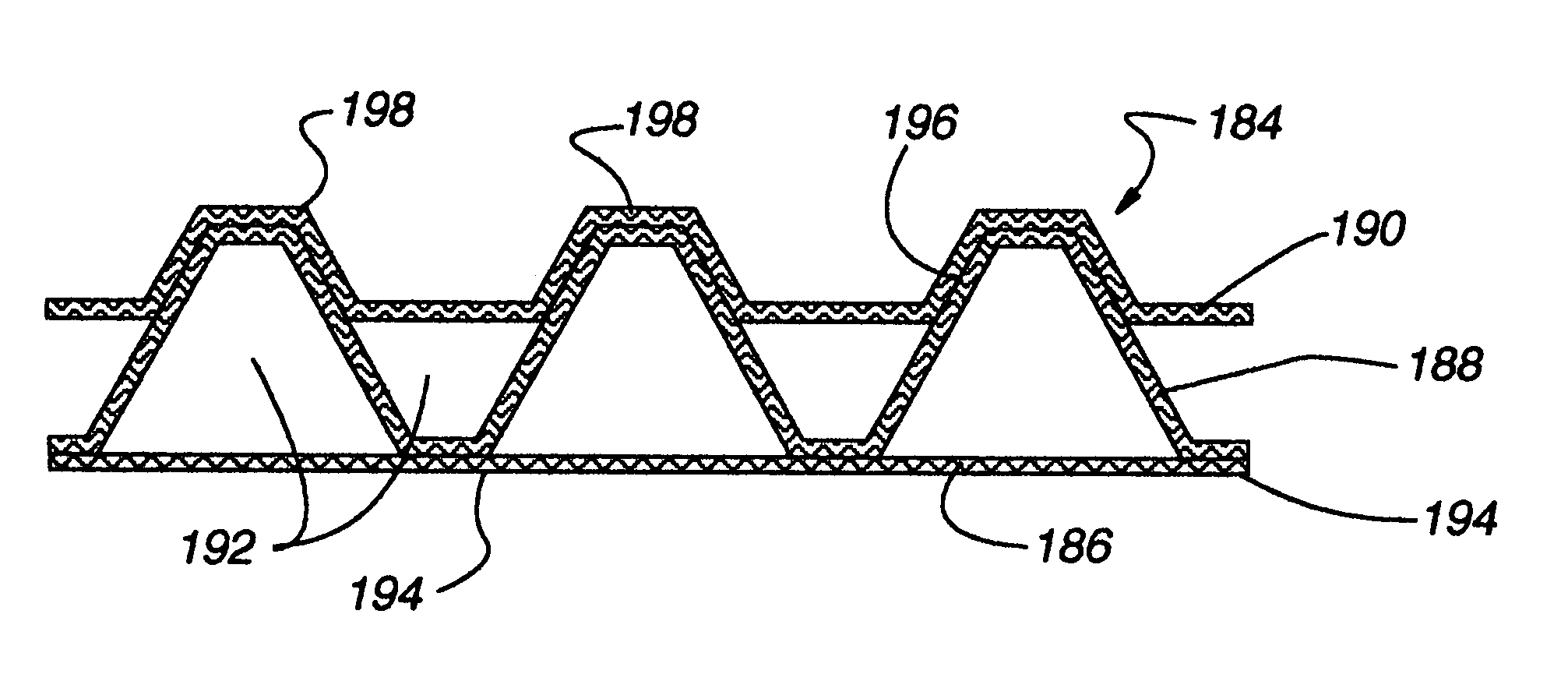
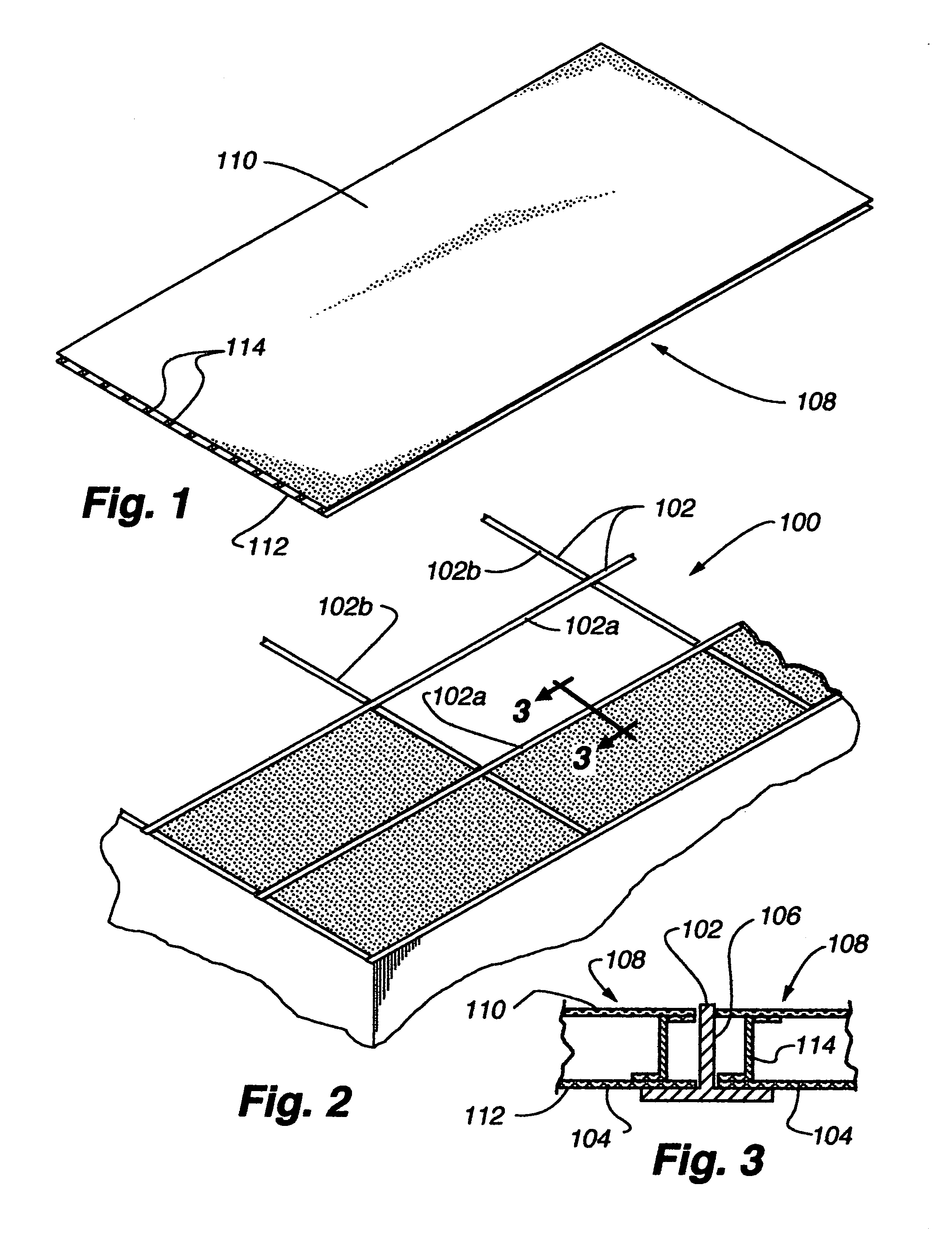
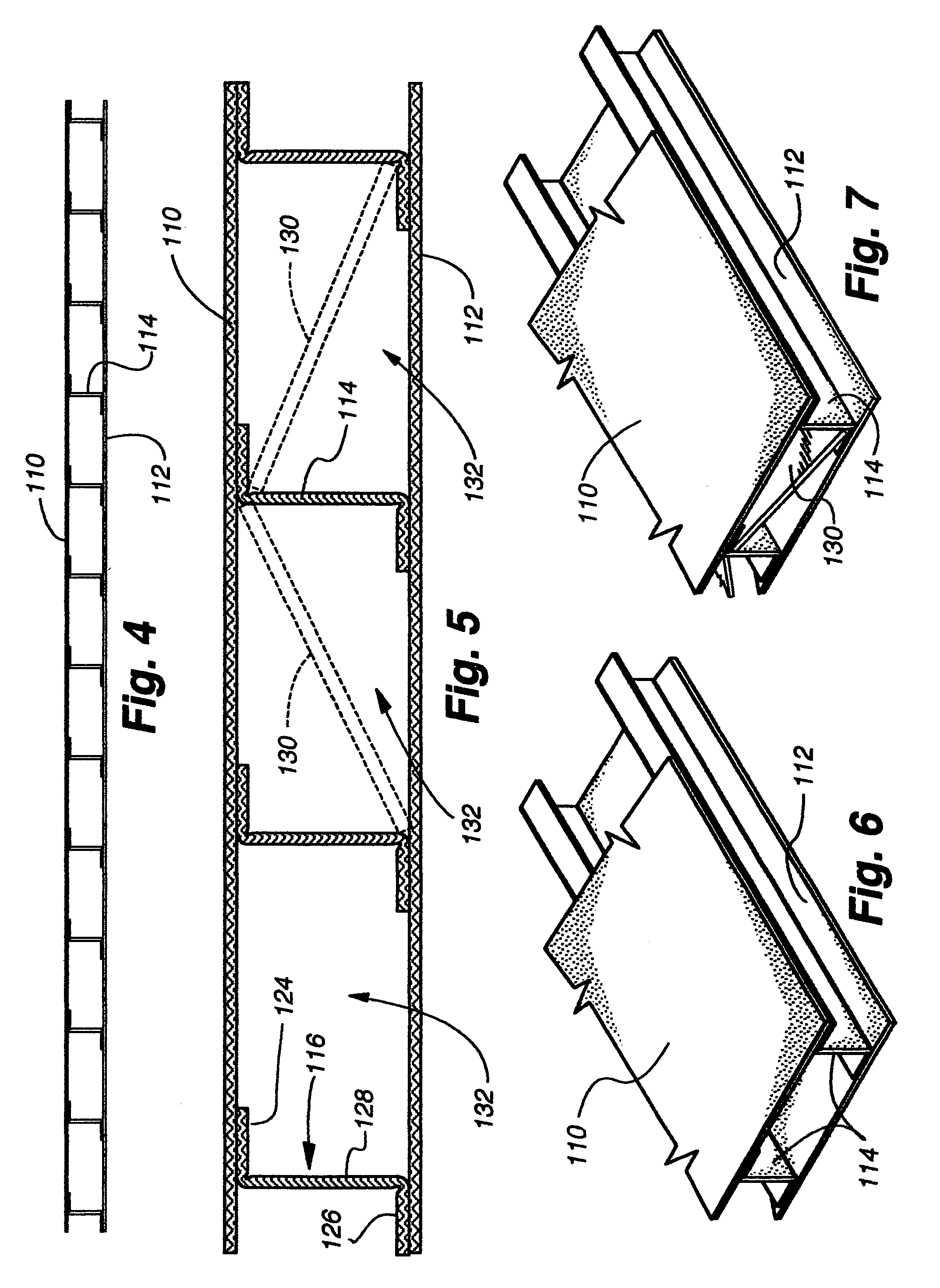
[0099]A drop ceiling system 100 in accordance with the present invention utilizes a conventional suspension system of elongated crisscrossing support members 102 forming a matrix defining openings that are usually rectangular in shape in which a panel in accordance with the present invention can be disposed. The support members typically consist of horizontally disposed elongated stringers 102a that are suspended in a conventional manner and in parallel relationship in one direction across a ceiling structure usually at a vertical spacing of four to six inches from the substructure of the building structure in which the ceiling system is mounted. A plurality of horizontal cross-support members 102b extend in parallel relationship and perpendicularly to the stringers so that the quadrangular openings are defined therebetween. The cross-members are also suspended at the same elevation as the stringers. The stringers and cross-members are of inverted T-shaped cross-section as illustrat...


PUM


Abstract

A panel for use in a drop ceiling system, or with appropriate modification, a wall, wherein the ceiling system includes stringers and cross-members defining areas therebetween for support of the panels wherein the panels include at least one planar sheet of material secured to a reinforcement member having channels formed therein to extend in at least one direction relative to the sheet material. When more than one sheet of material is used, the sheets of material are disposed on opposite sides of the reinforcement member. The panels are flexible for easy insertion into the openings between the stringers and cross-members of the support system and are readily compressed into a thinner profile for shipping purposes.

Description

CROSS REFERENCE TO RELATED APPLICATION[0001]This application claims priority to U.S. provisional application No. 60 / 148,834, filed Aug. 13, 1999. This application is hereby incorporated by reference as if fully disclosed herein.BACKGROUND OF THE INVENTION[0002]1. Field of the Invention[0003]The present invention relates to coverings for the ceilings and walls of building structures and, more particularly, to a drop ceiling or a wall panel wherein individual panels are supported on a matrix of support members.[0004]2. Description of the Relevant Art[0005]The ceilings of building structures have taken numerous forms. Ceilings may be left unfinished so that rafters or beams of the building structure itself are exposed or the rafters and beams may be covered as with drywall, wood strips, plaster or other similar finishes. Walls of building structures may be similarly finished.[0006]Another popular ceiling system is commonly referred to as a drop ceiling where a plurality of support bars...

Claims


Application Information

Patent Timeline
Patent Type & Authority Patents(United States)
IPC IPC(8): E04C2/32
CPCE04B9/0442E04B9/064E04B9/24Y10T428/24174Y10T428/24149Y10T428/236
Inventor SWISZCZ, PAUL G.KUPERUS, KO
Owner HUNTER DOUGLAS INC
Why Eureka
Try Eureka