
Image recording material separating/removing device

a technology of image recording and separating device, which is applied in the direction of de-stacking articles, packaging goods, transportation and packaging, etc., can solve the problems of complex structure of the device, complex locus of movement of the pick-up mechanism, and increased size of the entire devi

Inactive Publication Date: 2006-05-30
FUJIFILM HLDG CORP +1
View PDF20 Cites 16 Cited by
  • Summary
  • Abstract
  • Description
  • Claims
  • Application Information

AI Technical Summary

Benefits of technology

The present invention provides an image recording material separating / removing device that can easily lift image recording materials up out of multiple cassettes using a single lift-out mechanism section and simple movement paths. The device keeps the space required for placement and withdrawal of cassettes as small as possible. The device includes multiple cassettes that can accommodate image recording materials in a stacked manner, and a conveying unit that can access each cassette to remove the image recording materials. One cassette is positioned at an offset position from a directly beneath cassette to facilitate access.

Problems solved by technology

However, in order to withdraw the cassettes, a space for withdrawing the cassettes must be provided in advance, and size of the entire device increases.
However, the locus of movement of the pick-up mechanism becomes complex.
Further, it has been thought to provide plural lift-out mechanism sections, but in this case, the structure of the device becomes complex, which is not preferable.

Method used


Image

  • Image recording material separating/removing device
  • Image recording material separating/removing device
  • Image recording material separating/removing device

Examples


Embodiment Construction

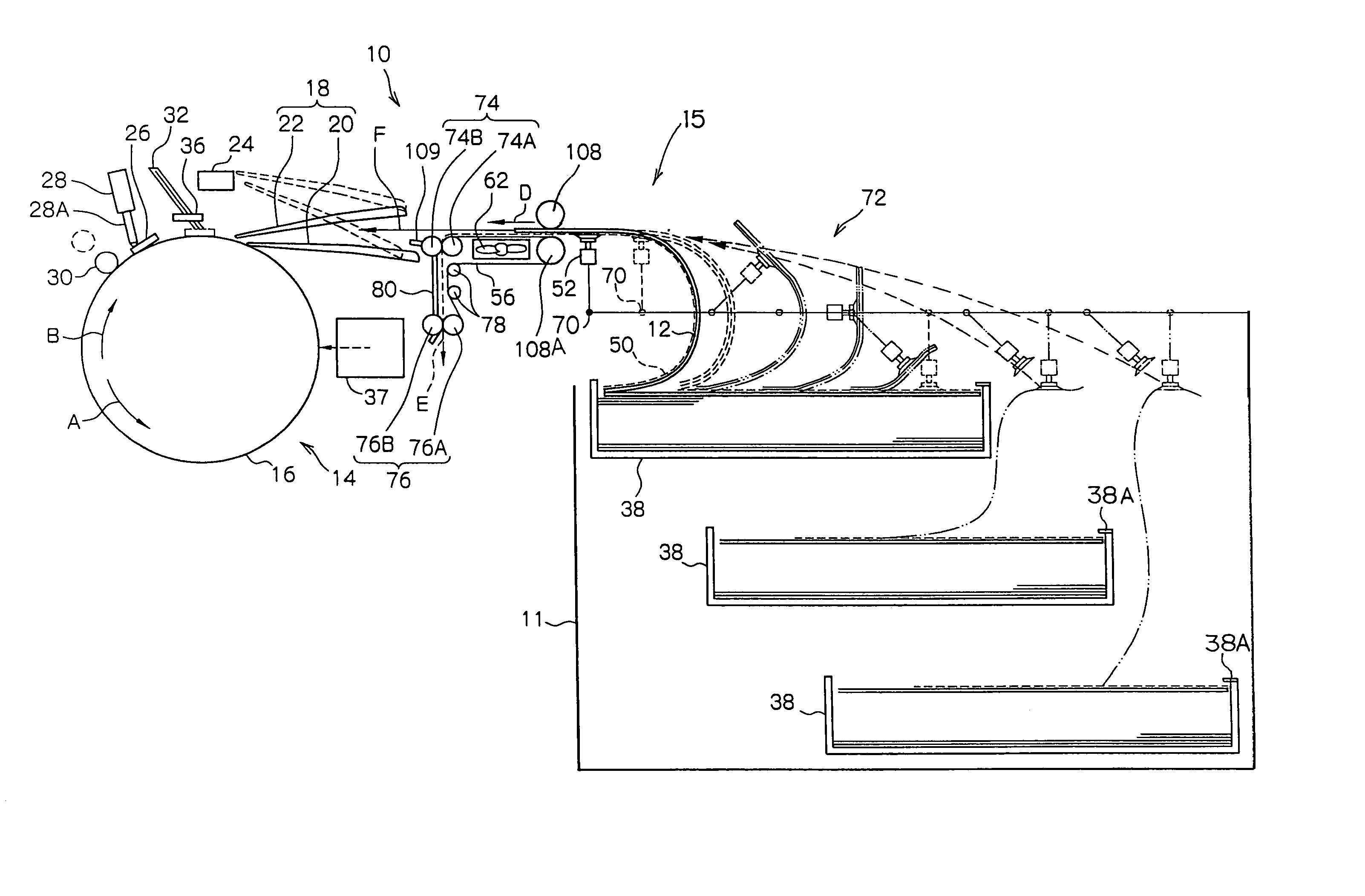
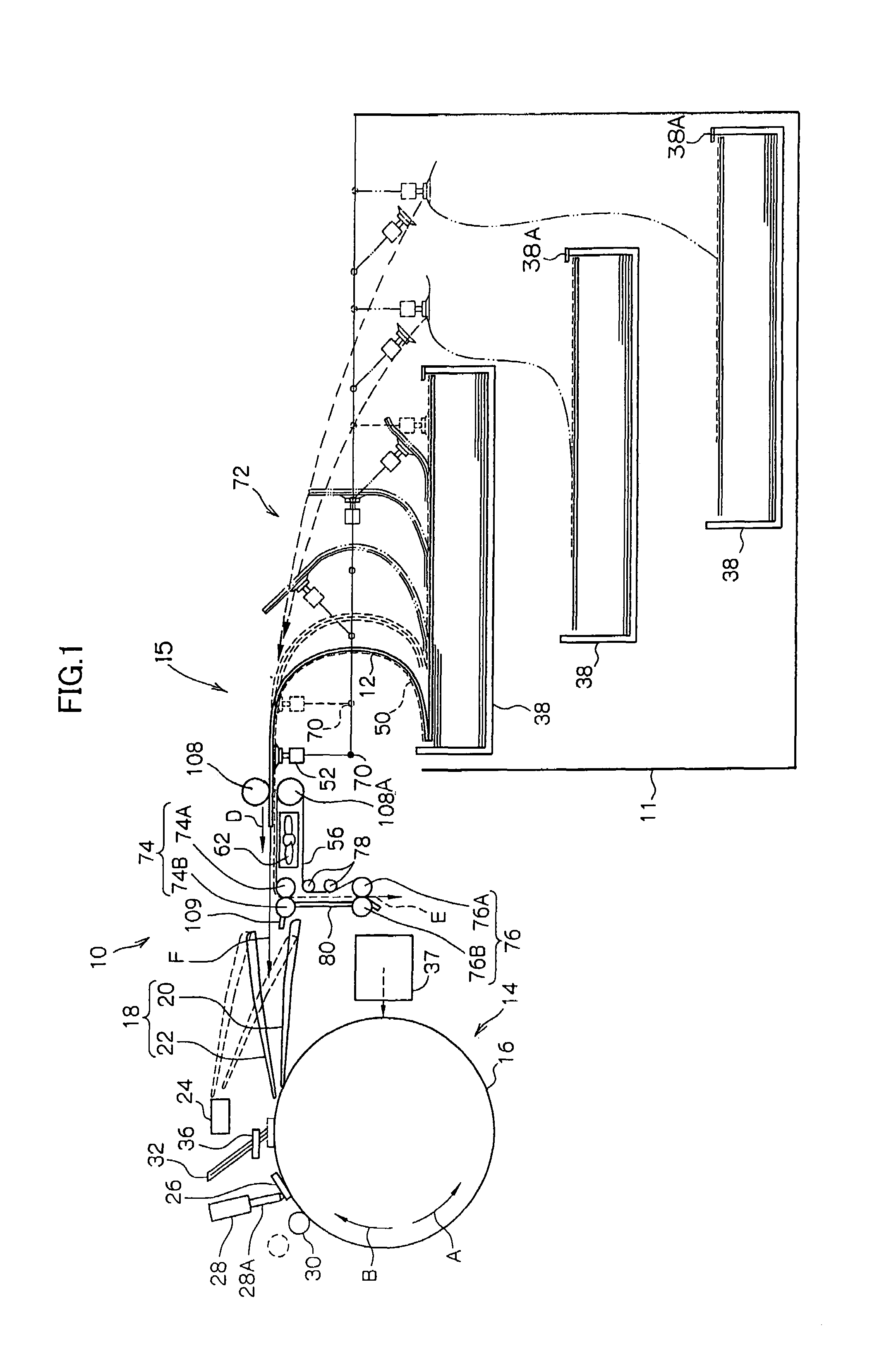
[0017]An automatic printing plate exposure device 10 relating to a first embodiment is shown in FIG. 1.

[0018]The automatic printing plate exposure device 10 is divided into two main sections which are an exposure section 14, which irradiates a light beam onto an image forming layer of a printing plate 12 so as to expose an image thereon, and a separating / removing / conveying section 15 which separates / removes the printing plate 12 and conveys the printing plate 12 to the exposure section 14. The printing plate 12, which has been subjected to exposure processing by the automatic printing plate exposure device 10, is fed out to a developing device (not illustrated) which is disposed adjacent to the automatic printing plate exposure device 10.

(Structure of Exposure Section)

[0019]The exposure section 14 is structured such that a rotating drum 16, around whose peripheral surface the printing plate 12 is trained and held, is the main portion of the exposure section 14. The printing plate 12...


PUM

PropertyMeasurementUnit
lengthaaaaaaaaaa
photosensitiveaaaaaaaaaa
sizesaaaaaaaaaa

Abstract

An image recording material separating / removing device which, by using a single lift-out mechanism section, can lift image recording materials out from plural cassettes along simple loci of movement, and in which a space for providing and withdrawing the cassettes is kept as small as possible. In a cassette housing section, a plurality of cassettes are disposed one above another. Each cassette is offset in a horizontal direction. An amount of offset is set on the basis of a locus of movement of a printing plate at a time when the printing plate is sucked and held by suction cups and lifted up in a vertical direction. At least while the suction cups are moving in the vertical direction, the printing plate is not interfered with by cassettes thereabove, and an emulsion surface of the printing plate is not scratched. Space required for placement of the cassette housing section can be reduced. Moreover, because movement of the suction cups can be simplified, a control system can be simplified.

Description

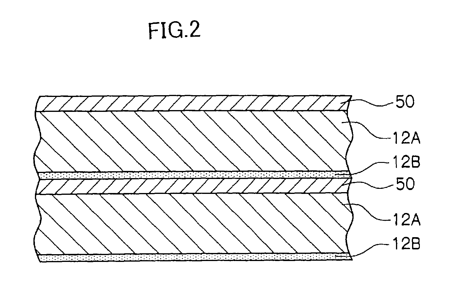
BACKGROUND OF THE INVENTION[0001]1. Field of the Invention[0002]The present invention relates to an image recording material separating / removing device equipped with a cassette in which image recording materials, in which an image recording surface is provided on a support, and interleaf sheets, which are thin-film-like and protect the image recording surfaces of the image recording materials, are accommodated in an alternately stacked manner. The image recording material separating / removing device discards the interleaf sheets accommodated in the cassette, and feeds the image recording materials to a subsequent process.[0003]2. Description of the Related Art[0004]A technique (printing plate exposure device) has come to be developed which, by using an image recording material (printing plate) in which an image recording surface (photosensitive layer) is provided on a support, records an image directly by a laser beam or the like onto an emulsion surface which serves as the photosens...

Claims


Application Information

Patent Timeline
Patent Type & Authority Patents(United States)
IPC IPC(8): B65H3/44B65H3/08B41C1/10G03F7/20B65H3/00B65H15/00
CPCB41C1/1083B65H3/02B65H3/0825B65H3/44B65H2701/1928B65H2405/332B65H2701/18264
Inventor ONO, TSUKASA
Owner FUJIFILM HLDG CORP
Learn More