Vehicular body panel or component part and method for manufacturing same

a technology for vehicle body panels and components, applied in vehicle arrangements, roofs, transportation and packaging, etc., can solve the problems of increasing the fabrication cost, reducing the reinforcement effect, and the backing plate formed of the curved plate encounters a problem, so as to improve the working efficiency

Inactive Publication Date: 2006-05-30
HONDA MOTOR CO LTD
View PDF31 Cites 14 Cited by
  • Summary
  • Abstract
  • Description
  • Claims
  • Application Information

AI Technical Summary

Benefits of technology

[0016]It is therefore a first object of the present invention to provide a vehicular body panel or component part and a method of manufacturing the same, which are capable of implementing a forming step in a single step without forming a gap between a hood frame and a backing plate.
[0018]The presence of the aperture formed in the backing plate at the position corresponding to the formed portion of the blank material permits the backing plate to preferably become integral or unitary with the blank material. That is, when forming the two components by bending operation, there is no fear in the backing plate from locally separating from the blank material to form the gap, with a resultant increase in a finishing quality of the vehicular body panel or the vehicular component part.
[0021]The term “formation” used herein means a plastic deformation processing such as bending, contracting and expanding. Below discussions will be made using “bending”, as an example. The employment of the backing plate formed with the aperture renders the blank material to be subjected to bending operation after the backing plate is reconciled thereto. Concurrent bending operation of the blank material and the backing plate enables the bending operation in a single step. In this event, it is possible to reduce the cost for bending operation by half as compared to the individual bending operations of the backing plate and the blank material.
[0023]The first backing plate is reconciled to the blank material in the blanking step. When it is required to reconcile the backing plate to the blank material in another site or in another step, although it is necessary to perform the transfer of the blank material or to prepare a stock place, the present invention makes it possible to render the blank material to be manufactured in the upper and lower blanking die halves such that the transfer of the blank material or the stock place are dispensed with for thereby providing a compactness in the equipment.
[0025]In a preferred form, the backing plate reconciling means includes a caulking mechanism having a cavity segment remaining on one side and a punch remaining on the other side such that two sheets, which are composed of the blank material and the backing plate placed thereon, are located between the cavity segment and the punch to allow the punch to thrust toward the cavity segment for thereby caulking the two sheets. Accordingly, the caulking with the punch and the cavity segment allows the working efficiency to be improved.

Problems solved by technology

In particular, although it has been a usual practice to employ a structure wherein a reinforcement plate, which is called as a backing plate, is attached to the steel panel with a view to mounting a hinge or striker to the hood panel, the presence of the backing plate formed of a curved plate encounters a problem during mounting the backing plate to the hood.
In such a conventional manufacturing method described with reference to FIGS. 19A and 19B, the bending operation should be implemented in two steps, with a resultant increase in the fabrication cost and a resultant decrease in the reinforcement effect owing to the gap created between the hood frame and the backing plate.
When trying to improve the yield of the raw material by cutting out a useful piece from the scrap portion in the aforementioned manner, it becomes necessary for a specific transfer means for the piece, a loss protective measure for the piece and the welding site in a large space to be provided, with a resultant increased cost in the equipment as well as an increase in an area for which the equipment is installed.

Method used


Image

  • Vehicular body panel or component part and method for manufacturing same
  • Vehicular body panel or component part and method for manufacturing same
  • Vehicular body panel or component part and method for manufacturing same

Examples


Embodiment Construction

[0048]The following description is merely exemplary in nature and is in no way intended to limit the invention, its application or uses.

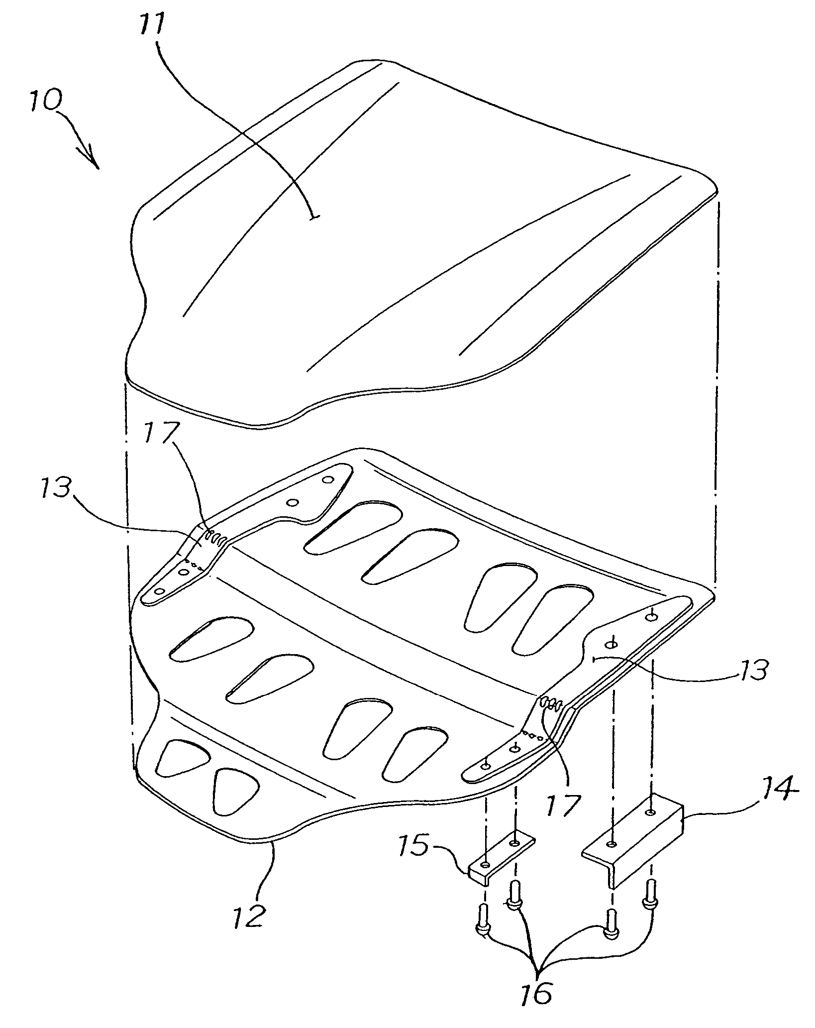
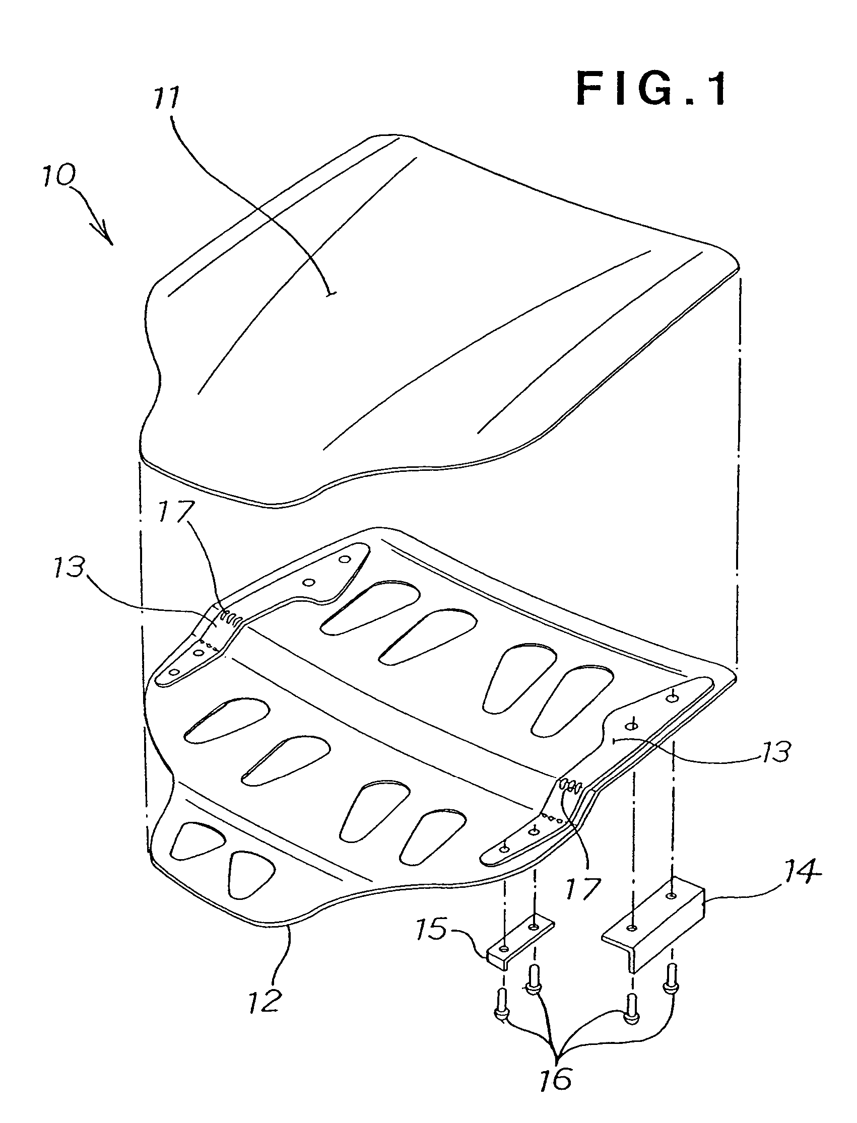
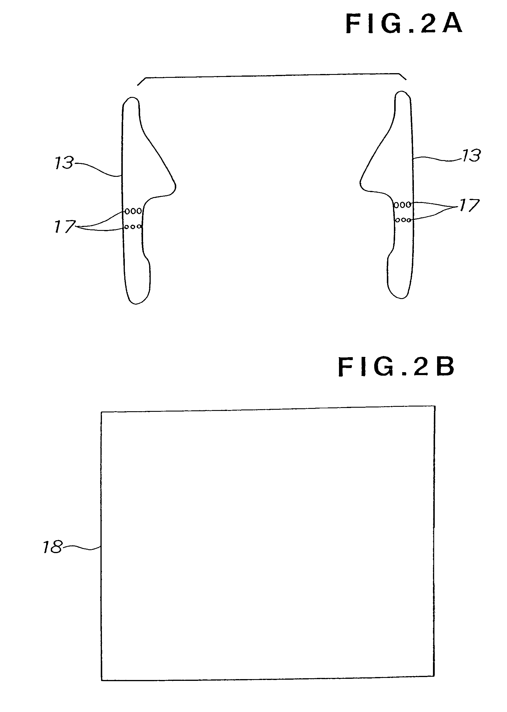
[0049]Referring now to FIG. 1, there is shown a hood 10 which is composed of a double-layered structure wherein an outer skin 11 is piled on an inner skin 12. Both side edge portions of an upper surface of the inner skin 12 have backing plates 13, 13, respectively. Brackets 14, 15 are fixedly secured to each of the backing plates 13, 13 by means of a plurality of bolts 16, respectively. The backing plates 13, 13 function to prevent the inner skin 12, which has a thin thickness, from being applied with a localized load which causes the inner skin 12 to be locally deformed, thereby reinforcing the inner skin 12 around its side edge portions. The inner skin 12, which is attached with the backing plates 13, 13, forms a first preferred embodiment of a vehicular body panel according to the present invention.

[0050]Now, a fabrication method of the inner ski...


PUM


Abstract

A vehicular body panel or component part having a reinforcing backing plate reconciled to a part of a blank material at a position wherein a bending formation is implemented. The backing plate has one or more apertures formed in at least one lateral raw at a location equivalent to the position of the bending formation. When forming the blank material and the backing plate concurrently by a bending operation, the backing plate becomes intimately associated with the blank sheet to avoid the backing plate from locally separating from the blank material and from forming a gap relative thereto, with a resultant improved product quality.

Description

BACKGROUND OF THE INVENTION[0001]1. Field of the Invention:[0002]This invention relates to an improvement in a technique for manufacturing a vehicular body panel or component part.[0003]2. Description of the Related Art:[0004]Japanese Patent Laid-Open Publication No. HEI-10-129527, for example, discloses a hood made of plastic resin material for use in an automobile. The hood has a closed cross sectional structure which is made of a product formed by a blow technique and which has an outer skin and a stiffener integral therewith. The outer skin has a main body section having a central portion extending in a widthwise direction of a vehicle body, two side edge portions located at both sides of the central position and extending in a longitudinal direction of the vehicle body, and two connecting portions interconnecting the central portion and the respective side edge portions. Each connecting portion includes a reinforcement rib extending from the stiffener and deposited onto the out...

Claims


Application Information

Patent Timeline
Patent Type & Authority Patents(United States)
IPC IPC(8): B62D25/10B62D65/00
CPCB62D65/00B62D25/105
Inventor KAMADA, TERUOTSUCHIYA, TAKASHIIWANAMI, NORIAKINUMANO, MASAMITSU
Owner HONDA MOTOR CO LTD
Why Eureka
Try Eureka