Rod integrator

a technology of integrators and rods, applied in waveguides, lighting and heating apparatuses, instruments, etc., can solve the problems of increasing the cost, size and weight of the display system, unable to detect the pulsing, and large light sources, so as to increase the brightness of the display system using the integrating rods

Inactive Publication Date: 2006-05-30
TEXAS INSTR INC
View PDF32 Cites 32 Cited by
  • Summary
  • Abstract
  • Description
  • Claims
  • Application Information

AI Technical Summary

Benefits of technology

[0016]The disclosed integrating rod not only homogenizes a beam of light passing through the integrating rod, it also recycles light rejected by a dynamic filter at the exit face of the in

Problems solved by technology

Increasing the light source, however, also increases the cost, size, and weight of the display system.
Additionally, larger light sources generate additional heat that must be dissipated by the display.
If the pixel is pulsed quickly enough, the human eye will accurately measure the average intensity of the pixel, but will fail to detect the pulsing.
The disadvantage of the three-modulator display system is the cost of the three modulators and the complex optics required both to split the white light beam from the light source into three primary color light beams and to recombine the modulated primary color l

Method used


Image

  • Rod integrator
  • Rod integrator
  • Rod integrator

Examples


Embodiment Construction

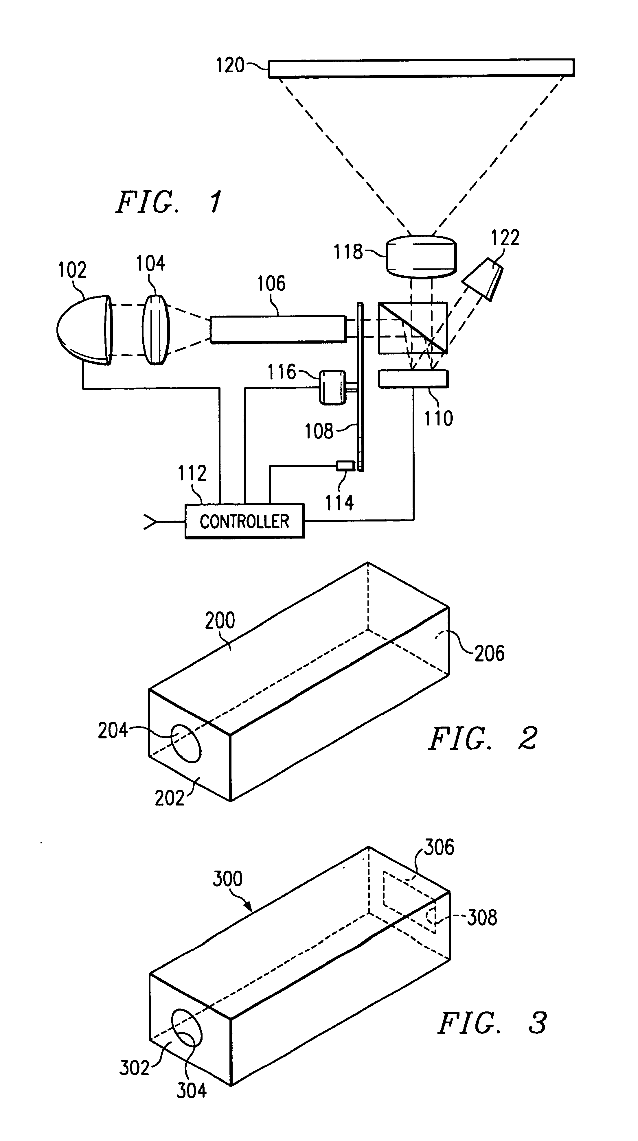
[0028]A new method and system of illuminating a light valve has been developed. The new method provides a white light beam to three or more unique portions of a dynamic color filter, typically a color wheel. Each portion of the dynamic filter allows a band of wavelengths to pass through the dynamic filter and rejects all wavelengths outside that band of wavelengths. The rejected wavelengths reenter the illumination system and are later represented to the dynamic filter. Upon the second and subsequent application of the rejected light to the dynamic filter, portions of the rejected light are accepted by the filter and used to illuminate a light valve. The light valve modulates the selected wavelengths to produce a modulated beam of light that is focused onto an image plane. Recycling the rejected wavelengths greatly increases the potential brightness of a display system without the use of a brighter light source or additional light valves and color splitters.

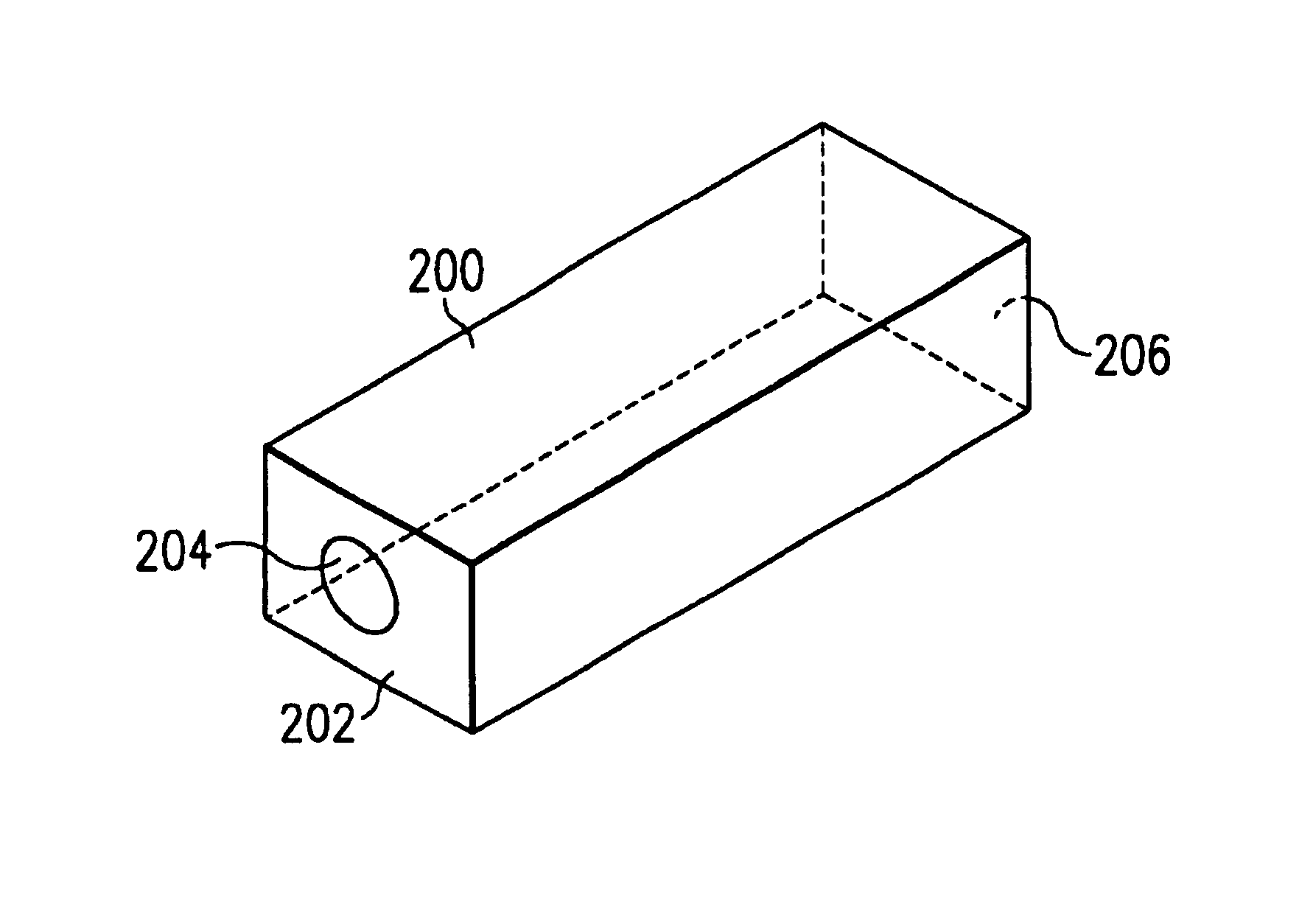
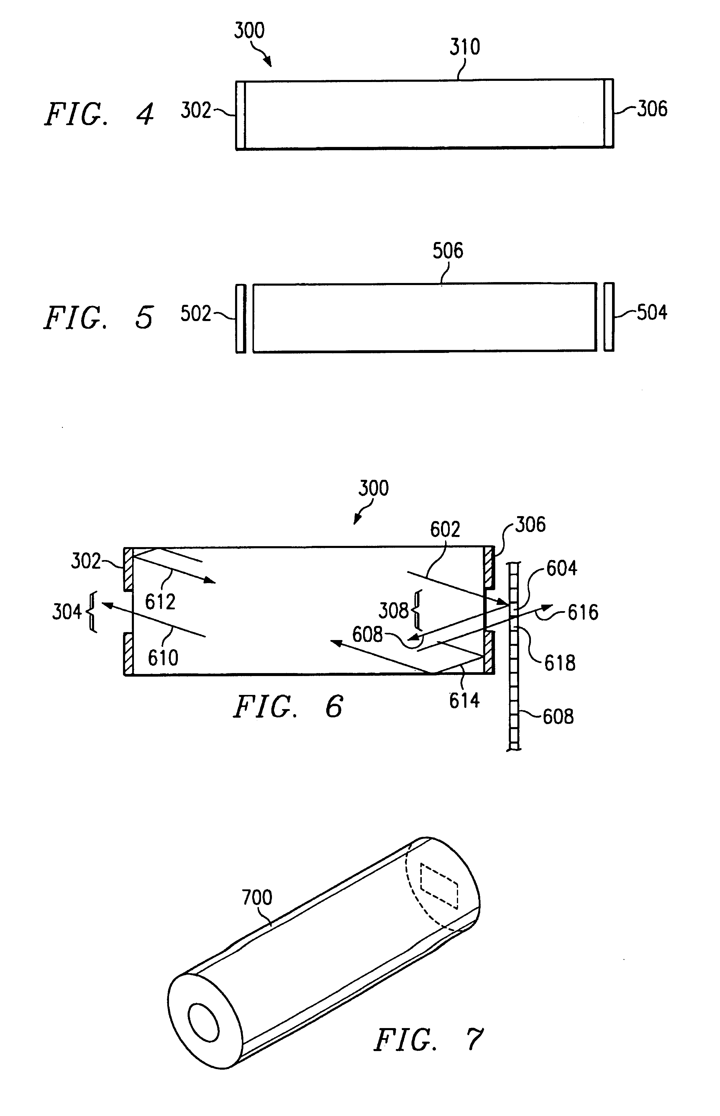
[0029]The novel integrati...


PUM


Abstract

An integrating rod (200) for use with a multiple segment dynamic filter, such as a spiral dichroic color wheel having three or more narrow filters adjacent to the exit face (206) to enable the integrating rod to recapture light rejected by a given segment of the dynamic filter. The rejected light travels back through the integrating rod where a majority of the light strikes the mirrored entrance face (202). Light reflected by the mirrored entrance face, or light exiting through the entrance aperture (204) and returning to the integrating rod after being reflected by the lamp reflector, once again travels to the exit face (206) of the integrating rod (200). After exiting through the exit face (206) of the integrating rod (200) a second time, the recycled light has a good chance of striking a different filter segment of the dynamic filter and being used by the display system.

Description

CROSS-REFERENCE TO RELATED APPLICATIONS[0001]This application claims priority under 35 USC§119(e)(1) of provisional application No. 60 / 173,942 filed Dec. 30, 1999.[0002]Patent No.Filing DateIssue DateTitleTI-29879Sequential Color Recapture forProjection SystemsTI-29914Color Wheel For A Falling RasterScanFIELD OF THE INVENTION[0003]This invention relates to the field of display systems, particularly to display systems using a rod integrator to homogenize a beam of light prior to modulating the beam of light using a light valve, more particularly to sequential color recapture display systems using an integrating rod to implement the light recapturing feature.BACKGROUND OF THE INVENTION[0004]Viewers evaluate display systems based on many criteria such as image size, resolution, contrast ratio, color purity, and brightness. Image brightness is a particularly important metric in many display markets since the available brightness can limit the image size of a projected image and controls...

Claims


Application Information

Patent Timeline
IPC IPC(8): G02B5/08G02B7/182G02B6/34G02B6/42G02B7/00G02B27/00G02B27/28G02F1/13357H04N9/31
CPCG02B6/4298G02B27/0927G02B27/0994G02B27/283G02B27/286H04N9/3117H04N9/3152H04N9/3167H04N9/3197G02B6/29361Y10S385/901G02B26/008G02F1/13362G02F2001/133622G02B6/29395G02F1/133622
Inventor DEWALD, DUANE SCOTT
Owner TEXAS INSTR INC
Why Eureka
Try Eureka