Method of lubricating multiple magnetic storage disks in close proximity

a magnetic storage disk and close proximity technology, applied in the field of lubricating disks, can solve the problems of affecting the lubricant's penetration into the space between the l-side surfaces, affecting the lubricant's penetration, so as to increase the volume of lubricated disks, increase the output of finished disks, and save substantial capital equipment.

Inactive Publication Date: 2006-05-30
MAXTOR
View PDF63 Cites 13 Cited by
  • Summary
  • Abstract
  • Description
  • Claims
  • Application Information

AI Technical Summary

Benefits of technology

[0030]These and other benefits are addressed by the various embodiments and configurations of the present invention. For example, a benefit provided by the present invention is an increased output in the production of finished disks achieved by lubricating multiple pairs of single-sided disks simultaneously. Another benefit is that, with limited modifications, the present invention can utilize existing processing equipment originally designed and built to lubricate double-sided disks for the processing of pairs of single-sided disks. By utilizing existing lu...

Problems solved by technology

In the first instance, depending upon the size of the gap between the disks, lubricant may not fully penetrate the space between the L-side surfaces of each pair of disks.
The viscosity of the lubricant can also affect this problem.
The closer the disks are to each other, the more pronounced this problem is.
If one or more pairs of disks are pulled into contact, th...

Method used


Image

  • Method of lubricating multiple magnetic storage disks in close proximity
  • Method of lubricating multiple magnetic storage disks in close proximity
  • Method of lubricating multiple magnetic storage disks in close proximity

Examples


Embodiment Construction

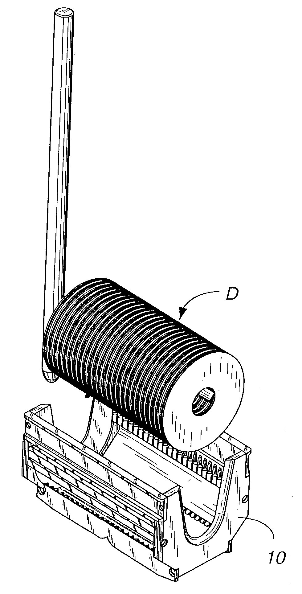
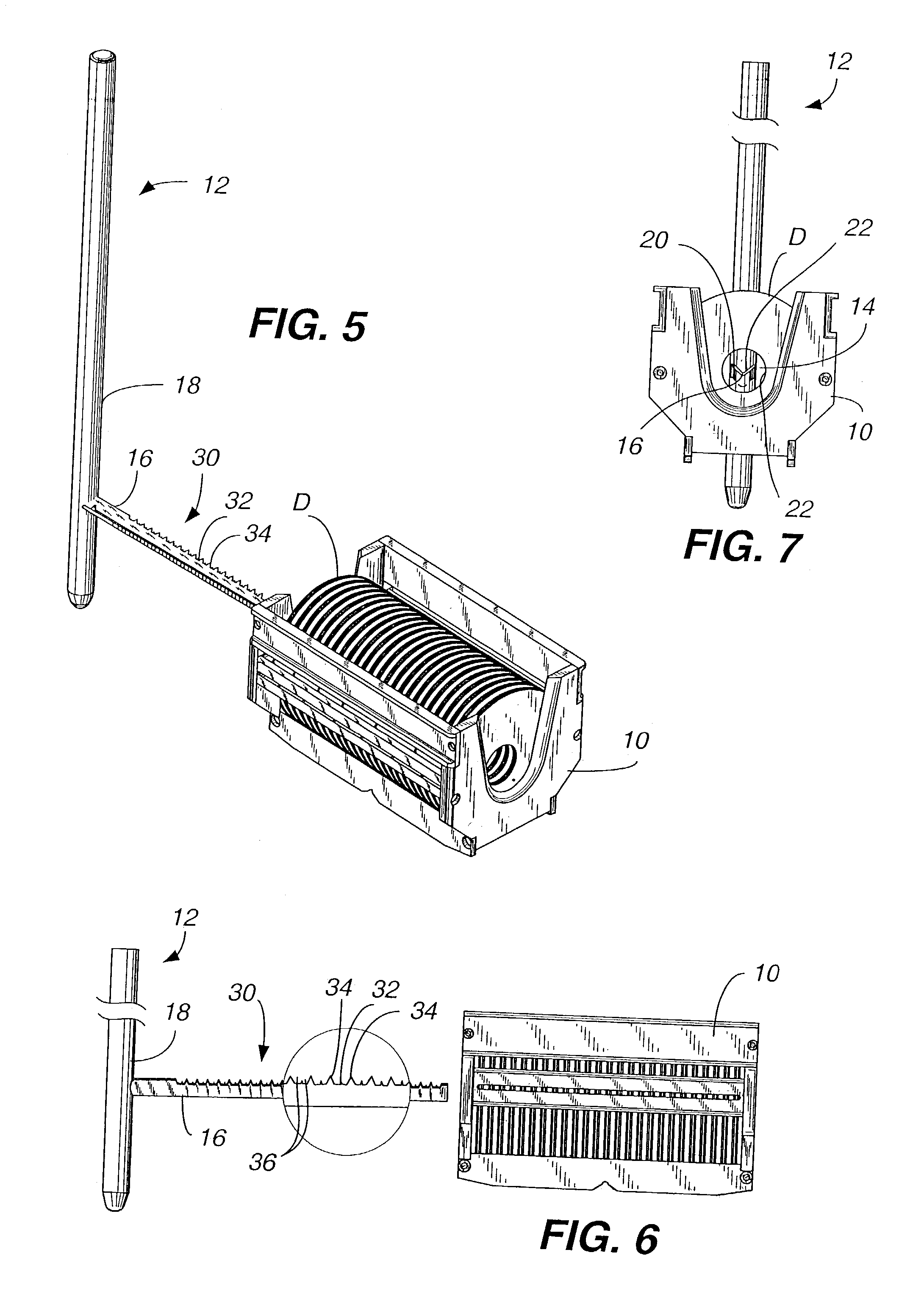
[0074]At some point during the manufacture of hard memory disks, the disks are subjected to a lubrication station. FIG. 5 shows a single row of disks D axially aligned in a cassette 10 or other suitable container. Although the disks are illustrated in a gap merge orientation, they could be equally spaced within the container or in some other orientation. As the lubrication process typically follows sputtering, the disks would likely exit the sputtering process in either a gap merge orientation or in an orientation with some space between the disks. This is because the sputtering process subjects the disks to significantly elevated temperatures which could cause the disks to physically weld themselves together if they were in contact. In the preferred embodiment, the disks will arrive at the lubrication station in pairs, with the pairs in a gap merge orientation. The gap spacing may vary depending upon the thickness and size of disks as would be appreciated by a person of skill in th...


PUM


Abstract

Various apparatus and methods are provided for lubricating hard memory disks. A mandrel is provided in one embodiment with three rows of teeth and provides a stable, three-point engagement with the inside edge of the disks at the center aperture. When removing disks from a cassette, the mandrel preferably places a uniform space between the disks. In a second embodiment, the mandrel may be used to lubricate single-sided hard memory disks. The single-sided hard memory disk may be positioned on the mandrel in pairs in a gap merge orientation, or equally spaced apart.

Description

CROSS REFERENCE TO RELATED APPLICATIONS[0001]Priority is claimed from U.S. Provisional Patent Application Ser. Nos. 60 / 378,972, filed May 9, 2002, and 60 / 417,668, filed Oct. 10, 2002, which are incorporated by reference herein in their entirety.[0002]The subject matter of the present application is related to the following applications, each of which has a filing date of May 9, 2003: U.S. patent application Ser. No. 10 / 434,550 entitled “Single-Sided Sputtered Magnetic Recording Disks” in the name of Clasara et al. (Publication No. US-2003-0211361-A1); U.S. patent application Ser. No. 10 / 435,361 entitled “Dual Disk Transport Mechanism Processing Two Disks Tilted Toward Each Other” in the name of Grow et al. (Publication No. US-2003-0208899-A1); U.S. patent application Ser. No. 10 / 435,358 entitled “Information-Storage Media With Dissimilar Outer Diameter and / or Inner Diameter Chamfer Designs On Two Sides” in the name of Clasara et al. (Publication No. US-2003-02 10498-A1); U.S. patent...

Claims


Application Information

Patent Timeline
IPC IPC(8): B05D1/18G11B23/00G11B23/50
CPCG11B23/505G11B23/00
Inventor BUITRON, GERARDOCHENG, PETERCROFTON, WALTERKIM, KWANG KONMAIDA, WILLIAMNEWMAN, DAVID
Owner MAXTOR
Why Eureka
Try Eureka