Insulated bus bar assembly in a voltage source converter

Inactive Publication Date: 2006-05-30
ABB (SCHWEIZ) AG
View PDF5 Cites 15 Cited by
  • Summary
  • Abstract
  • Description
  • Claims
  • Application Information

AI Technical Summary

Benefits of technology

[0011]Yet another object is to provide a bus bar assembly, having an insulation inserted

Problems solved by technology

Considering the voltage levels applied between the bars, typically in the order of 10–20 kV or more, it is a problem to secure sufficient insulation in the narrow gaps that are formed between the conductor bars.
The method is suffering from a limited acces

Method used


Image

  • Insulated bus bar assembly in a voltage source converter
  • Insulated bus bar assembly in a voltage source converter

Examples


Example

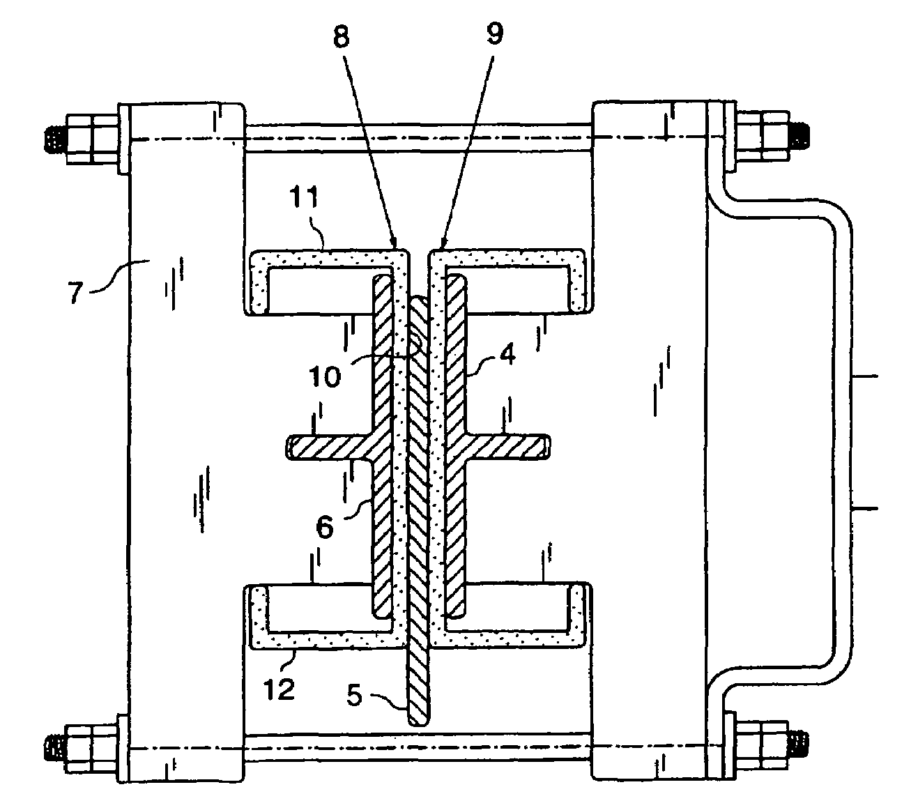
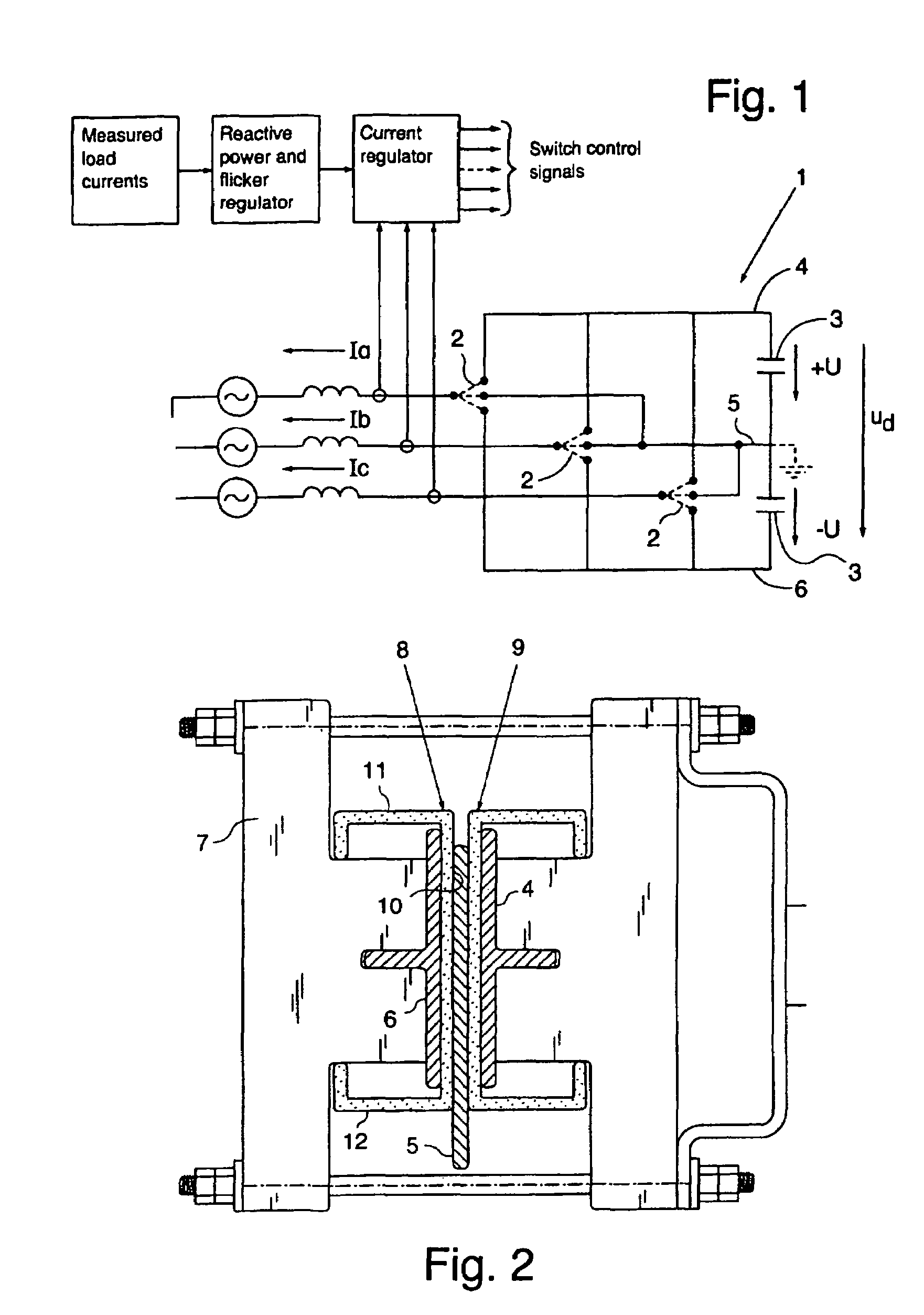
[0017]Referring to FIG. 1, an AC / DC-converter 1 is diagrammatically shown in a voltage source converter system (VSC). In the AC / DC-converter 1, switches 2 are controlled to switch either one of the three levels of voltage on the DC-side (+U, O, −U) into each AC-phase (Ia, Ib, Ic). The switches are controlled relative to measured load currents, and are operative for injecting corrective current into each phase of the network. A high switching frequency is desirable for achieving fast response—the implementation of IGBT converter valves provides a turn-off capacity reaching switching frequencies up to approximately 3,000 operations per second. To arrive at such fast commutation of current in the converter valves, it is of crucial importance to keep inductance low on the direct current side of the converter.

[0018]The direct current side of the converter 1 comprises a DC capacitor package 3, from which current is supplied through the converter valves or switches 2. In order to keep indu...


PUM


Abstract

The invention relates to a voltage source converter system, and includes a plane parallel bus bar assembly having conductor bars closely related for reducing induced voltage in the assembly. Each gap that is formed between adjacent conductor bars is completely filled by a polymer insulator which is formed for providing complete freedom of access to fully exposed external sides of the bus bar assembly. The invention also relates to a molded, single piece polymer insulator including an elongate rib member of continuous height and thickness, and elongate wing members angularly extended from each longitudinal periphery of the rib member.

Description

TECHNICAL BACKGROUND[0001]The invention relates to a voltage source converter system, and more specifically to a plane parallel bus bar assembly that is designed to allow high switching frequencies of a direct voltage component in the system. The invention also relates to the insulation of conductor bars incorporated in the bus bar assembly, and to a voltage source converter incorporating the bus bar assembly.[0002]As used herein, “high switching frequencies” relates to frequencies reaching the order of approximately 1,500 Hz.[0003]In the course of providing high quality electrical power and stabilized grid voltage, Voltage Source Converters (VSC) have been developed to control the magnitude, phase and frequency of the three phase AC-voltage. The VSC provides a capacity both to generate and absorb reactive power, mitigating voltage fluctuations generated by variations in loads and thus restoring voltage and current balance in the grid.[0004]The main task for the voltage source conve...

Claims


Application Information

Patent Timeline
IPC IPC(8): H02G5/00H02G5/02H02M7/00
CPCH02M7/003H02G5/025
Inventor BJORKLUND, ANDERSLARSSON, TOMASBERGSTROM, TOMMY
Owner ABB (SCHWEIZ) AG
Why Eureka
Try Eureka