Torsional acoustic wave sensor

a technology of acoustic wave and torsional wave, applied in the field of torsional wave sensor, can solve the problems of metal and the like not being used, piezoelectric element relatively unprotected, and high price of switch typ

Inactive Publication Date: 2006-05-30
TEXZEC
View PDF20 Cites 18 Cited by
  • Summary
  • Abstract
  • Description
  • Claims
  • Application Information

AI Technical Summary

Problems solved by technology

Further, the enclosure through which touch is sensed cannot be made of an electrically conducting material, so that metals and the like cannot be used.
This type of switch is expensive compared to a standard membrane switch and shares the disadvantages of membrane switches in that holes in the housing or enclosure are required to accommodate the switch.
Further, the metal overlay is necessarily thin, so that the piezoelectric element is relatively unprotected against blows to the overlay.
This type of switch is relatively expensive and again requires openings in the housing or enclosure in which the switch is to be mounted.
As such, the ratio of the stored energy to lost or dissipated energy over a complete cycle, referred to as the Q of the switch, is inherently low and an extremely complex touch detection circuit is required to discriminate between a touch and the absence of a touch.
Moreover, the use of compressional waves in this switch is undesirable due to their sensitivity to liquids and other contaminants which can render the switch inoperable.
These systems are undesirable, however, because surface acoustic waves are sensitive to liquids, sealing compounds and other contaminants that can render the panel inoperable and difficult to seal effectively.
Although this touch position sensor is insensitive to liquids and contaminants, touch position sensors that use reflective gratings or arrays and the associated touch detection circuitry are, in general, too expensive to use for an individual switch or for a small number of switches on a panel.
As a result of this sensitivity, when the shear acoustic wave switch is used in the presence of water, the level of which varies, such as when the switch is used outdoors in rain, the water can cause the switch to have a response that flickers.
However, the cylindrical body, in which the torsional wave is trapped, greatly limits the application and use of trapped torsional modes.

Method used


Image

  • Torsional acoustic wave sensor
  • Torsional acoustic wave sensor
  • Torsional acoustic wave sensor

Examples


Embodiment Construction

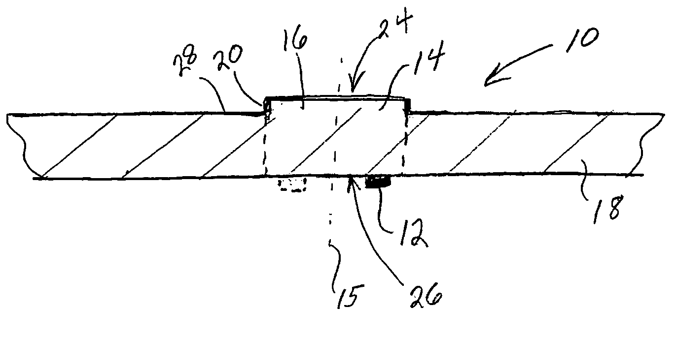
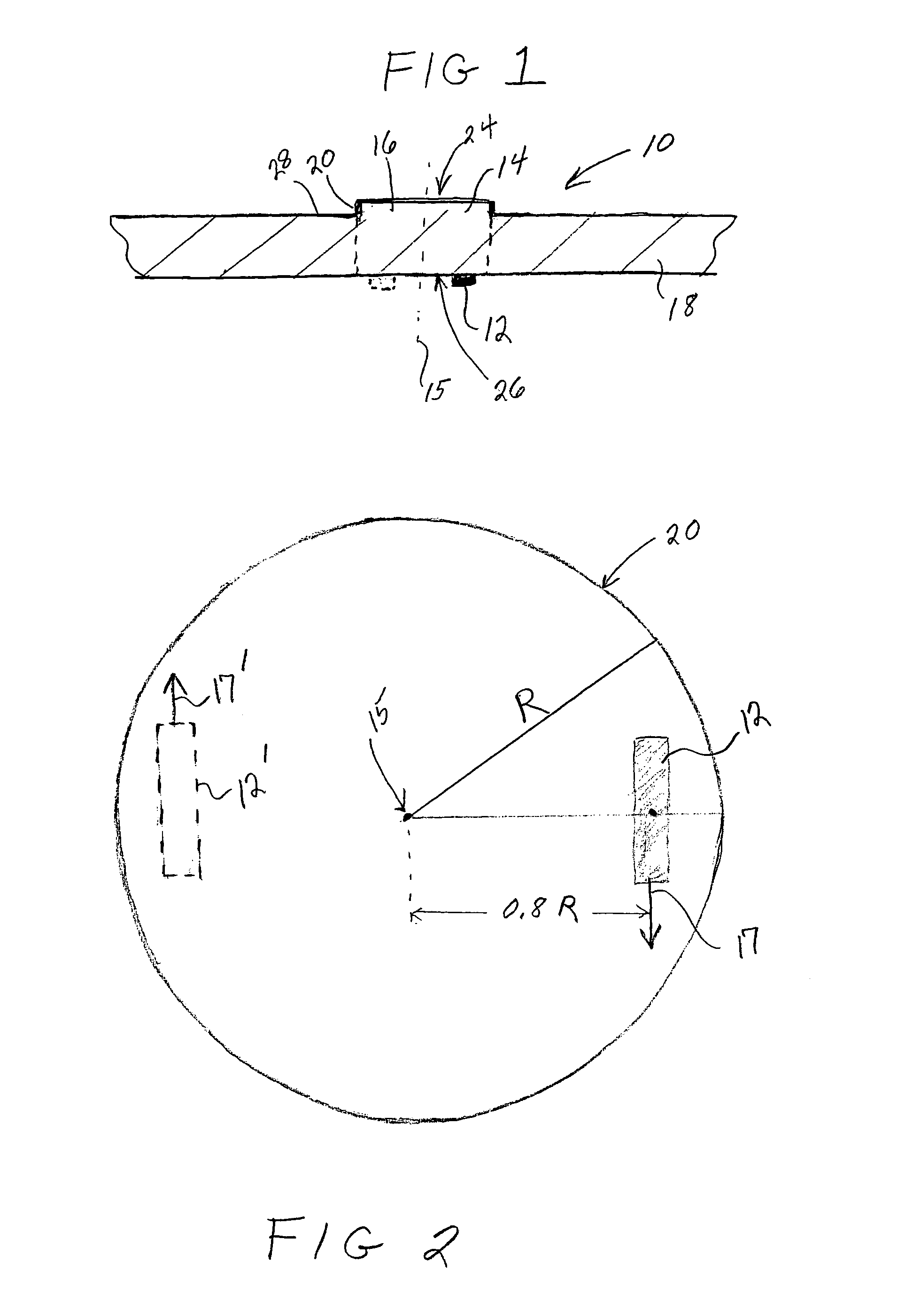
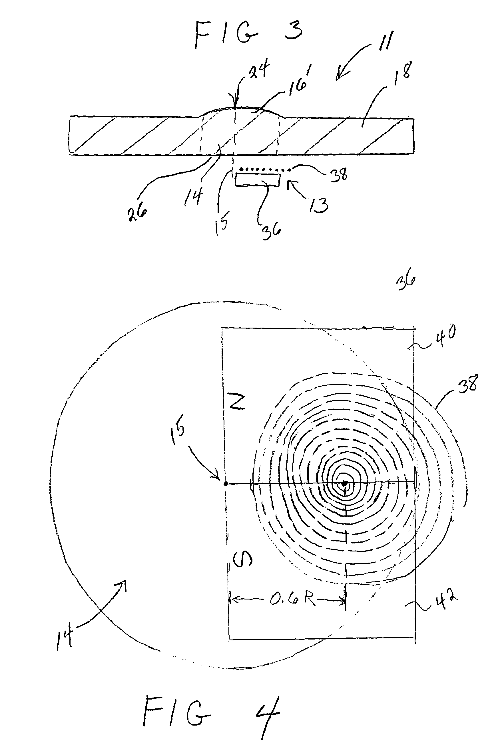
[0022]An acoustic wave sensor or resonator 10, 11, in accordance with the present invention as shown in FIGS. 1–4, includes a transducer 12, 13 positioned adjacent an acoustic wave cavity 14 such that the transducer 12, 13 is off-center with respect to the centerline 15 of the cavity 14 so as to generate a trapped or resonant torsional acoustic wave in the acoustic wave cavity 14. The acoustic wave cavity 14 is formed in a noncylindrical substrate 18 wherein the transducer 12, 13 generating the trapped torsional acoustic wave is in a plane that is parallel to a planar surface 26 of the acoustic wave cavity 14. It has been found that a trapped, torsional acoustic wave generated in accordance with the present invention is insensitive to water. That is, an acoustic wave touch sensor, for example, utilizing a trapped torsional wave generated in accordance with the present invention will not erroneously register a sensed event when only water is present where the water is at a level that...


PUM


Abstract

An acoustic wave sensor / resonator utilizes a torsional wave trapped in an acoustic wave cavity that is formed in a noncylindrical substrate. An acoustic wave transducer is positioned adjacent the acoustic wave cavity off of the centerline of the cavity and in a plane parallel to a planar surface of the acoustic wave cavity to generate the torsional wave. The acoustic wave transducer can be a piezoelectric transducer or an electromagnetic transducer. Further, the torsional wave can be generated by a single transducer or multiple transducers.

Description

CROSS-REFERENCE TO RELATED APPLICATIONS[0001]This application is related to the following patent applications: U.S. patent application entitled “Acoustic Wave Touch Actuated Switch,” Ser. No. 09 / 998,355, filed Nov. 20, 2001; U.S. patent application entitled “Acoustic Wave Sensor With EMAT Drive,” Ser. No. 10 / 245,246, filed Sep. 17, 2002; and U.S. patent application entitled “Acoustic Wave Touch Detection Circuit and Method,” Ser. No. 10 / 454,003 filed Jun. 4, 2003.STATEMENT REGARDING FEDERALLY SPONSORED RESEARCH OR DEVELOPMENT[0002]N / AFIELD OF THE INVENTION[0003]The present invention relates to an acoustic wave sensor that utilizes a trapped acoustic wave that is sensitive to an event such as a touch but that is insensitive to water and to variations in water level and more particularly to an acoustic wave sensor or resonator that utilizes a torsional wave trapped in an acoustic wave cavity formed in a noncylindrical substrate.BACKGROUND OF THE INVENTION[0004]There is a substantial n...

Claims


Application Information

Patent Timeline
Patent Type & Authority Patents(United States)
IPC IPC(8): H01L41/08H03K17/96
CPCH03K17/96A61B8/485H03K2217/96011
Inventor KNOWLES, TERENCE J.
Owner TEXZEC
Why Eureka
Try Eureka