
Surface acoustic wave sensor methods and systems

a surface acoustic wave and sensor technology, applied in the field of sensing methods and systems, can solve the problems of large chip size, increased production cost, and preventing the effective implementation of such devices

Inactive Publication Date: 2007-01-23
HONEYWELL INT INC
View PDF21 Cites 36 Cited by
  • Summary
  • Abstract
  • Description
  • Claims
  • Application Information

AI Technical Summary

Benefits of technology

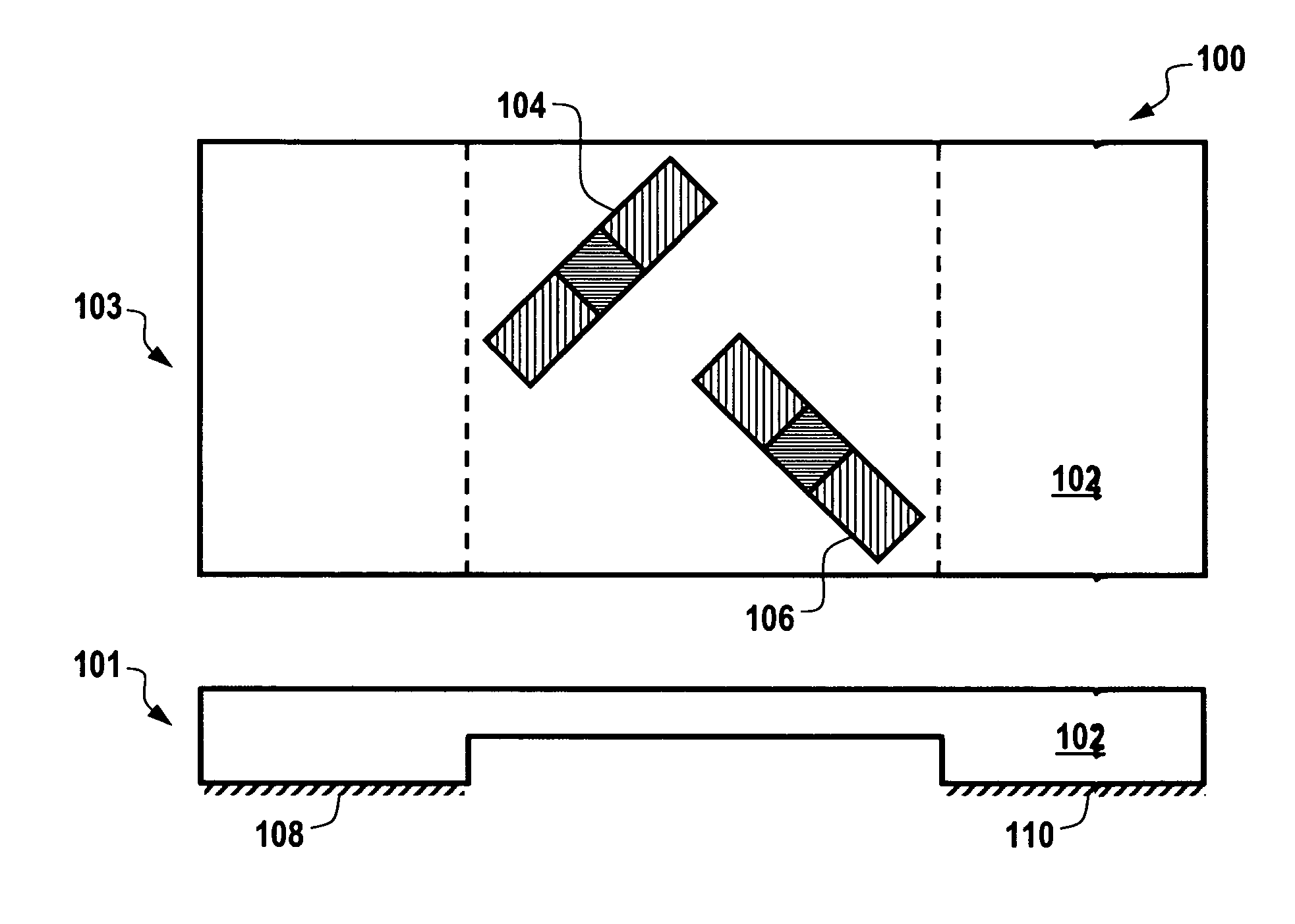
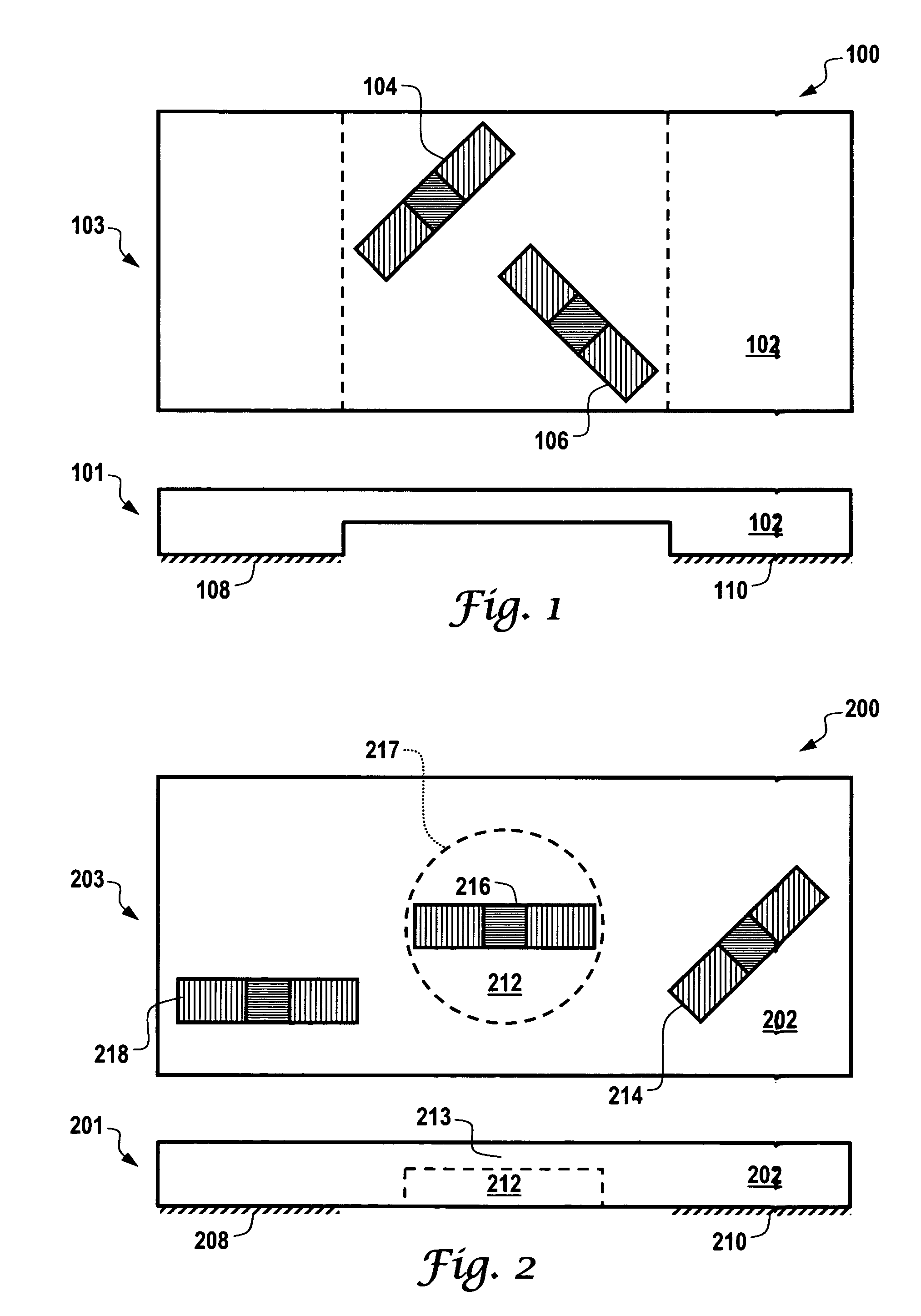
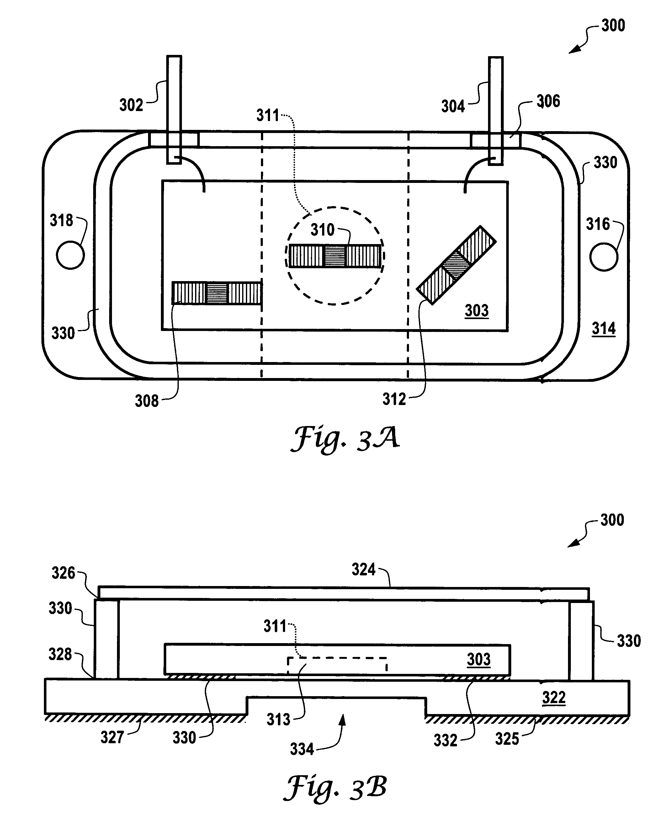
The present invention provides improved sensor-based systems and methods. Specifically, the invention includes a sensor chip with at least two surface acoustic wave (SAW) sensing elements located on the front side of the chip. An etched diaphragm is located on the back side of the chip opposite the SAW sensing elements to concentrate the mechanical strain of the sensor system. The sensor chip can be made from swept quartz and the SAW sensing elements composed of interdigital transducers (IDTs). The diaphragm can be etched using wet or dry etching methods. The changes in frequency, phase, or amplitude associated with the sensor chip correlate with the mechanical strain. Overall, the invention provides high strength, high sensitivity, and ease of manufacturing for the sensor system.

Problems solved by technology

To date, however, technological hurdles have prevented such devices from being effectively implemented.
A number of problems, however, are associated with conventional sensor applications.
The use of such devices, however, results in increased production costs, larger chip sizes and is difficult to micro-machine.
Existing designs therefore require large substrate and circuit sizes, and also expensive calibration processes during production.

Method used


Image

  • Surface acoustic wave sensor methods and systems
  • Surface acoustic wave sensor methods and systems
  • Surface acoustic wave sensor methods and systems

Examples


Embodiment Construction

[0019]The particular values and configurations discussed in these non-limiting examples can be varied and are cited merely to illustrate embodiments of the present invention and are not intended to limit the scope of the invention.

[0020]Embodiments disclosed herein generally describe a methodology for the mechanical design of an etched quartz diaphragm for torque, pressure and / or temperature sensing, along with general techniques for deep quartz etching, direct quart-to-quartz packaging, and metal connections, which protrude external to a quartz cage. Such concepts can be applied to sensing configurations based on an implementation of a plurality of SAW resonators.

[0021]The two SAW resonators or SAW delay lines can be at least partially on a sensing diaphragm. The SAW resonators or SAW delay lines should be located perpendicular to each other to form the half bridge for the torque strain measurement.

[0022]Prior to the design and fabrication of a wireless and / or passive quartz-based ...


PUM


Abstract

Sensor systems and methods are disclosed herein, including a sensor chip, upon which at least two surface acoustic wave (SAW) sensing elements are centrally located on a first side (e.g., front side) of the sensor chip. The SAW sensing elements occupy a common area on the first side of the sensor chip. An etched diaphragm is located centrally on the second side (i.e., back side) of the sensor chip opposite the first side in association with the two SAW sensing elements in order to concentrate the mechanical strain of the sensor system or sensor device in the etched diagram, thereby providing high strength, high sensitivity and ease of manufacturing thereof.

Description

TECHNICAL FIELD[0001]Embodiments are generally related to sensing methods and systems. Embodiments are also related to micromachined sensing devices. Embodiments are additionally related to surface acoustic wave (SAW) devices and sensors. Embodiments are additionally related to torque, pressure and / or temperature sensors.BACKGROUND OF THE INVENTION[0002]Surface acoustic wave sensors can be utilized in a variety of sensing applications, such as torque, pressure and / or temperature detection. Such sensors can be implemented, for example, by locating surface acoustic wave (SAW) device on an etched diaphragm within a piezoelectric material such as quartz. To date, however, technological hurdles have prevented such devices from being effectively implemented. Currently, a strong demand exists to utilize torque, pressure and / or temperature sensors in harsh environments or in association with rotating parts.[0003]Attempts have been made to implement pressure sensing devices. A number of prob...

Claims


Application Information

Patent Timeline
Patent Type & Authority Patents(United States)
IPC IPC(8): H03H9/25
CPCG01L1/165G01L9/0025G01L3/10
Inventor MAGEE, STEVEN J.COOK, JAMES D.LIU, JAMES Z.
Owner HONEYWELL INT INC
Learn More