
Real-time ranging and angle measurements using radar and surface acoustic wave transponders

Active Publication Date: 2011-04-12
MASSACHUSETTS INST OF TECH
View PDF3 Cites 40 Cited by
  • Summary
  • Abstract
  • Description
  • Claims
  • Application Information

AI Technical Summary

Benefits of technology

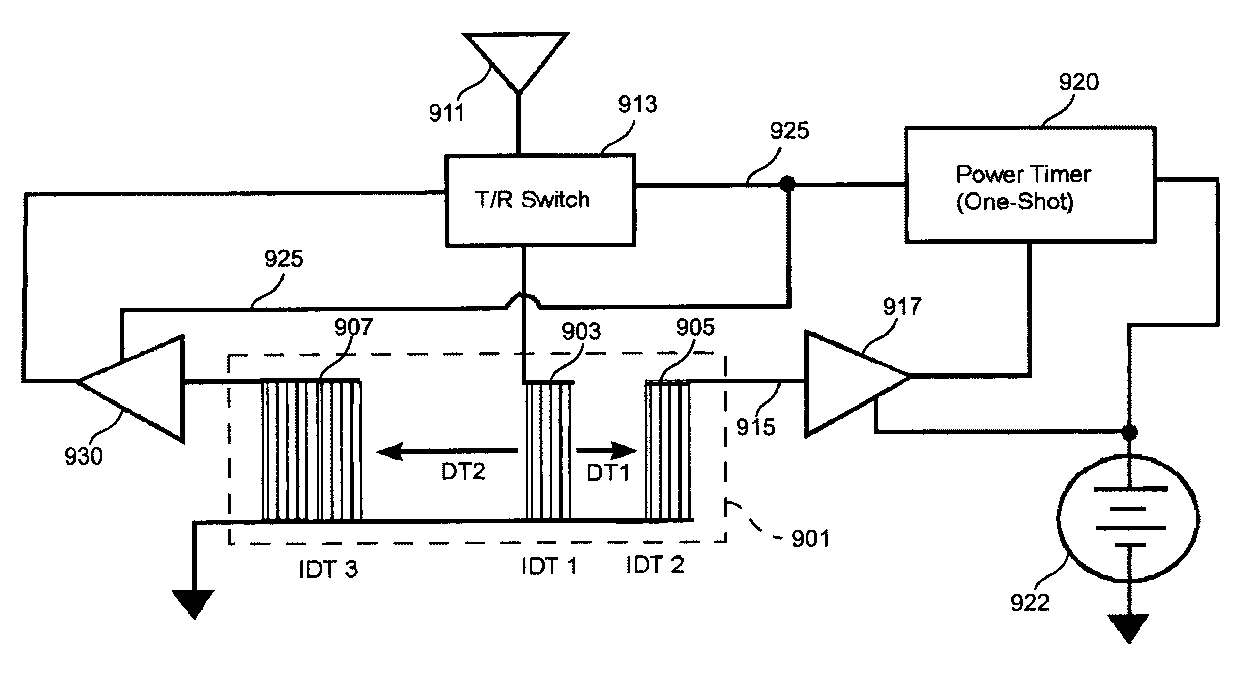
[0014]In accordance with the invention, the SAW devices passively process the received signals and thereby encode the returned signals with unique identifying characteristics without the need for electronic processing or modulating circuitry, thereby minimizing the cost, complexity and size of the transponders. To augment the range of the transponders, the passive SAW device may be combined with a normally inactive amplifier that is activated briefly in response to receipt of an incoming electromagnetic signal from an interrogating transmitter to amplify the returned signal, and then returns to an inactive power conservation state. This will allow a small battery to provide power for boosting the return transmission with greatly extended life.
[0015]The resulting SAW device transponders can be very small (e.g. 10 mm×10 mm—an order of magnitude smaller than conventional tags used in prior art tracking systems) and hence can be used in large numbers to provide multiple tracking points when needed by applications such as tracking the complex motions of the human body. Moreover, the SAW transponders may be inexpensively manufactured (e.g. $1 or $2 each when made in volume quantities, permitting the use of large numbers of tags at a reasonable cost). Further, the fast response time of the SAW transponders permits them to be used at high tracking rates (e.g. 150 kHz). Still further, the SAW transponders can be accurately tracked in the presence of environmental interference and radar clutter.
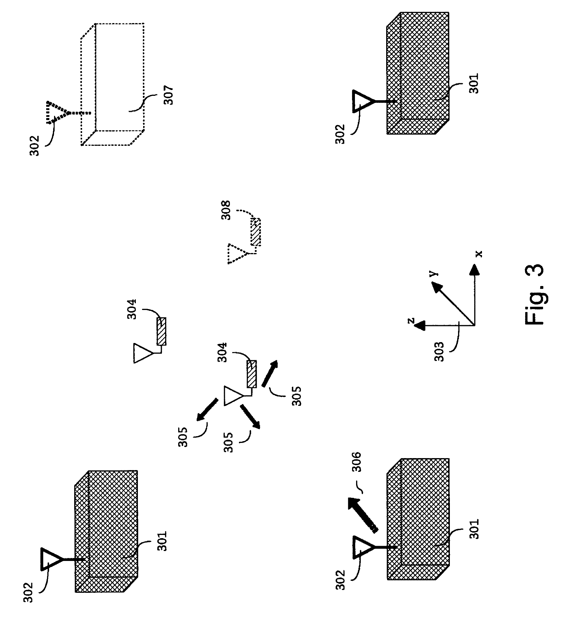
[0018](a) objects may be accurately located in three dimensional space within a relatively short-range (0-100 m) of a measurement station in real time.
[0019](b) a transponder attached to each tracked object employs a surface acoustic wave device to produce a return signal having a wave shape that uniquely identifies the particular transponder and does so without requiring electronic signal processing circuitry;

Problems solved by technology

Ultrasonic transponders are bulky, require a power source, and have limited line-of-sight constraints and their performance is greatly compromised by typical environmental interference.
Inertial measurement units are bulky, costly, require a power source, and are limited by bandwidth and accuracy.
These techniques require a potentially bulky transponder that need an on-board battery.
Unfortunately the transponders used in the Lanzi et al. system employ complex solid-state electronic circuitry to respond to and process the incoming signal, to produce encoded response signals that uniquely identify each transponder, and to retransmit the encoded signals to the reading stations.
The resulting passive and active tags are expensive to manufacture, tend to be bulky, exhibit slow response times which limit the system's ability to track rapidly moving objects in real time, have limited range and, in the case of passive tags, require a wireless power station to supply operating potentials to the on-board solid state signal processing circuitry.

Method used


Image

  • Real-time ranging and angle measurements using radar and surface acoustic wave transponders
  • Real-time ranging and angle measurements using radar and surface acoustic wave transponders
  • Real-time ranging and angle measurements using radar and surface acoustic wave transponders

Examples


Embodiment Construction

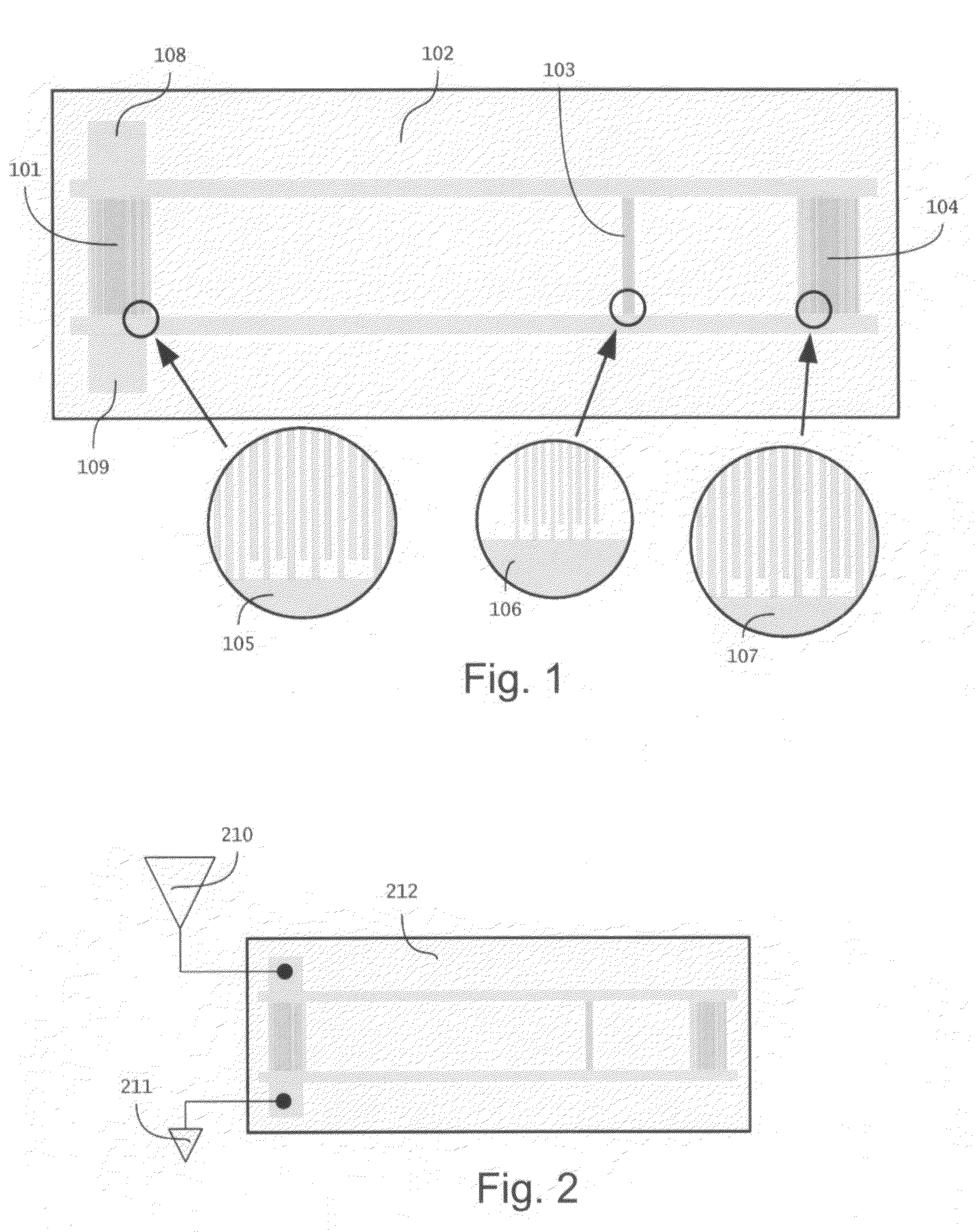
[0034]Tracking the position and motion of objects is desirable in numerous applications that require or would benefit from methods and apparatus capable of tracking rapidly moving objects with high resolution and high data rates. The preferred embodiments of the invention fulfill this need by using small Surface Acoustic Wave (SAW) transponders, which are referred to here as “microtags,” that are attached to movable objects and that are tracked by a distributed radar tracking network. The radar network tracks the location of the SAW transponders in three-dimensional space with an update rate, or number of samples per second, on the order of 10 kHz with an accuracy to within 10 cm3 or better in an optimized implementation.

[0035]Surface Acoustic Wave devices were originally developed in the 1960's and are generally described by H. Matthews in “Surface Wave Filters: Design, Construction, and Use,” New York: John Wiley & Sons, 1977, and by C. K. Campbell in “Surface Acoustic Wave Device...


PUM


Abstract

A system for tracking the position of multiple objects in three dimensional space by transmitting radar interrogation signals having predetermined wave shapes to surface acoustic wave transducers attached to each object. Each transducer includes a unique electrically conductive pattern on one surface of a piezoelectric substrate for selectively responding to the predetermined wave shape of one of the interrogation signals for inducing a surface acoustic wave in the substrate and for thereafter transforming the surface acoustic wave into an electromagnetic response signal having detectable properties that uniquely identify said transducer. The location of each transducer is estimated by measuring the time-of-flight or angle-of-arrival of the radar signals at several measurement stations and producing a position estimate by triangulation.

Description

CROSS REFERENCE TO RELATED APPLICATIONS[0001]This application is a non-provisional of, and claims the benefit of the filing date of, U.S. Provisional Patent Application Ser. No. 60 / 779,879 filed on Mar. 7, 2006, the disclosure of which is incorporated herein by reference.FIELD OF THE INVENTION[0002]This invention relates to methods and apparatus for determining the location of objects.BACKGROUND OF THE INVENTION[0003]Many applications need to detect the position and motion of multiple objects in three dimensional space. For example, methods for tracking the movement of different parts of the human body can be used in computer-aided design, training systems, virtual environments, medical diagnosis and therapy, computer game control, mobile platform coordination, and robotic control. Three dimensional tracking of animals may be used for behavioral and gait studies or wildlife tracking, and three dimensional tracking of the motion of physical objects may be used in security, inventory ...

Claims


Application Information

Patent Timeline
IPC IPC(8): G08B13/14G08B1/08
CPCG08B13/2422G01S5/04G01S5/14G01S2205/01
Inventor LAPENTA, JASON M.PARADISO, JOSEPH A.
Owner MASSACHUSETTS INST OF TECH
Learn More