Feed forward amplifier

a forward amplifier and amplifier technology, applied in amplifiers, amplifiers with semiconductor devices/discharge tubes, amplifiers, etc., can solve the problems of increasing the overall cost and complexity of the ffa circuit, requiring additional care, cost and/or complexity, and increasing the overall cost and complexity of the ffa design. to achieve the effect of reducing cost and complexity

Inactive Publication Date: 2006-05-30
WI LAN INC
View PDF18 Cites 10 Cited by
  • Summary
  • Abstract
  • Description
  • Claims
  • Application Information

AI Technical Summary

Benefits of technology

[0009]In another aspect of the present invention, there is provided a feed forward amplifier comprising: an amplifier portion having a main amplifier and an error correction pathway; a pilot tone generator-receiver having an oscillator for producing a signal; a vector modulator connected to said oscillator and for either adding or subtracting a modulating frequency to or from, respectively, said signal in order to generate a pilot tone suitable for injection prior to said main amplifier; and, a receiver circuit connected to said oscillator and for detecting a pilot tone from an output of said feed forward amplifier to control said error correction pathway in order to

Problems solved by technology

While the use of a pilot tone can improve the overall linearity of FFAs, current pilot tone generators and receivers tend to add complexity and overall cost to the FFA circuit.
Another problem with using two oscillators is that phase noise, (jitter in the time domain) can exist between the oscillators, thus requiring additional care, cost and/or complexity when designing both the generator an

Method used


Image

  • Feed forward amplifier
  • Feed forward amplifier
  • Feed forward amplifier

Examples


Embodiment Construction

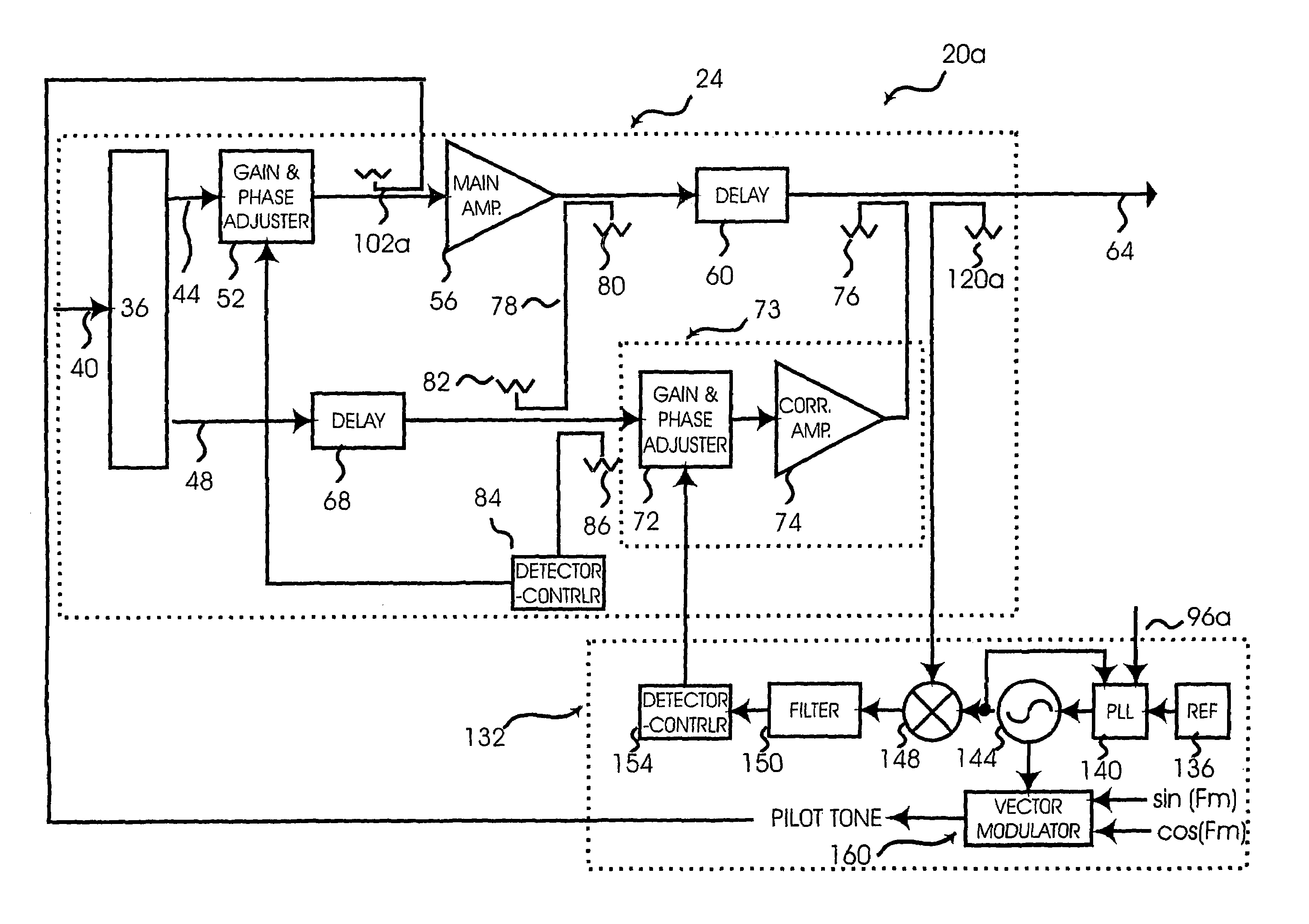
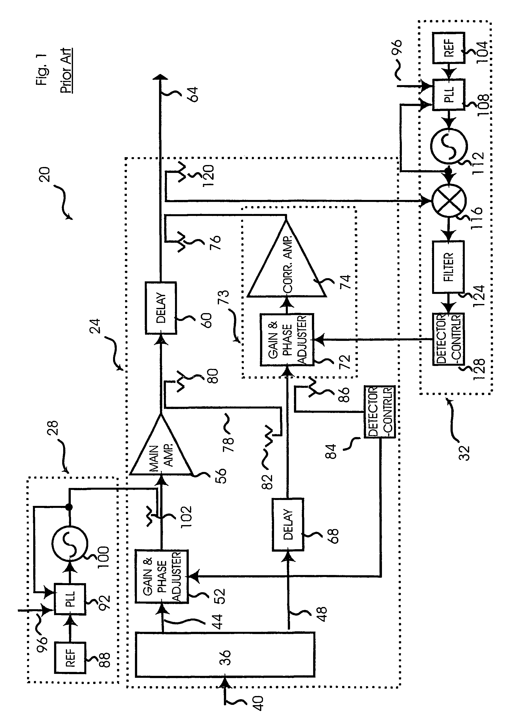
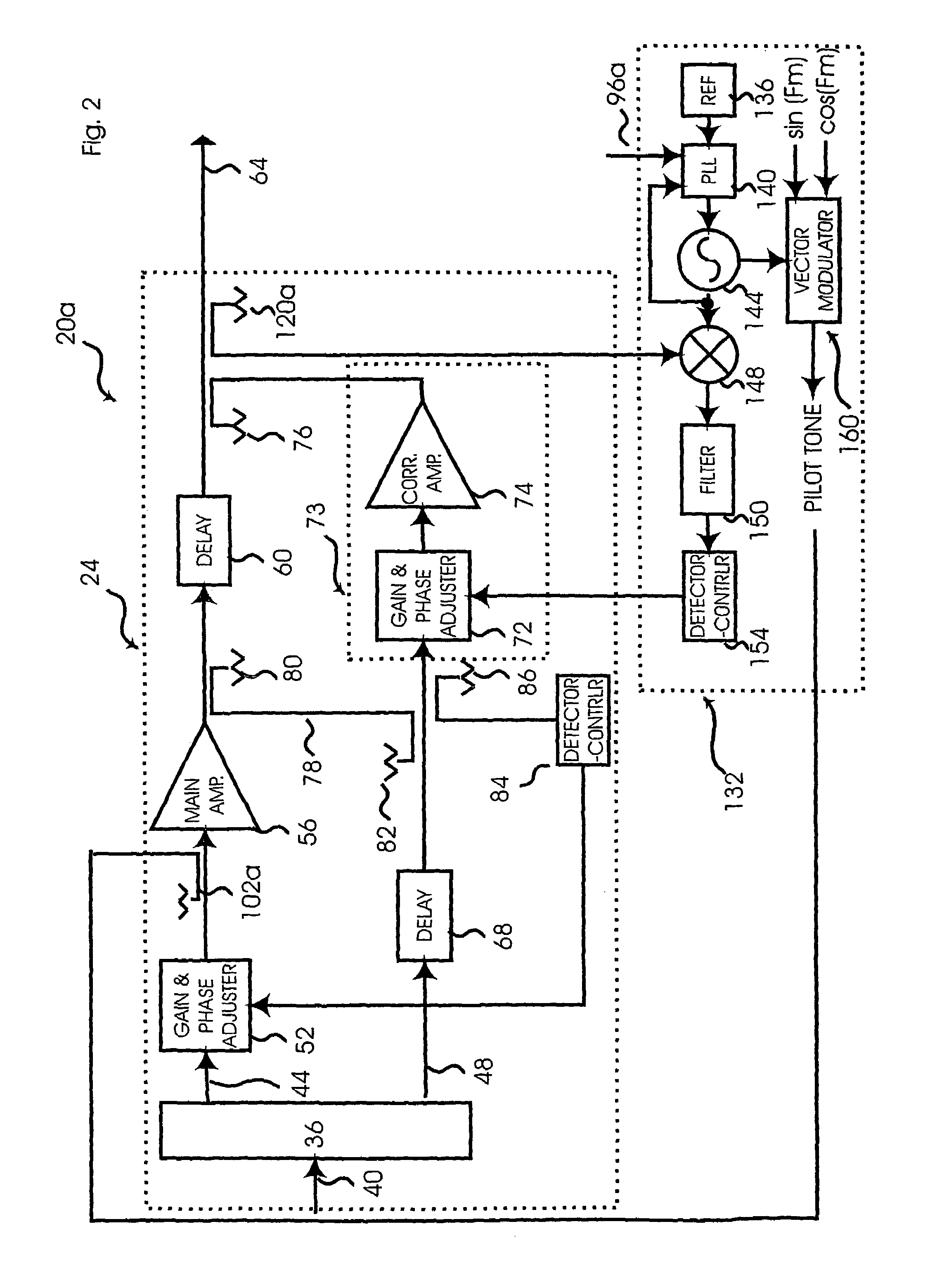
[0015]Referring now to FIG. 1, a prior art feed forward amplifier (“FFA”) is indicated generally at 20. FFA 20 comprises an amplifier portion 24, a pilot tone generator 28, and a pilot tone receiver 32.

[0016]Amplifier portion 24 includes a coupler 36 that is connected to an input signal path 40. Coupler 36 is operable to split an incoming signal from path 40 into a first signal path 44 and a second signal path 48. First signal path 44, which carries the main signal from coupler 36, is characterized by a gain and phase adjuster 52, a main amplifier 56 and a delay element 60 that outputs to an output signal path 64. Second signal path 48, which carries a sample of the input signal generated by coupler 36, is characterized by a delay element 68, a gain and phase adjuster 72 and a correctional amplifier 74, the output of which connects to output signal path 64 via a coupler 76. Those of skill in the art will recognize that adjuster 72 and correctional amplifier 74 form an error correcti...


PUM


Abstract

The present invention provides a novel feed forward amplifier (“FFA”) and a pilot tone generator-receiver therefor. In an embodiment of the invention, the feed forward amplifier only requires a single oscillator to operate both the pilot tone generator and pilot tone receiver used in conjunction with the amplifier circuitry of the FFA. In another embodiment of the invention, a method is provided of generating and detecting a pilot tone from a single oscillating signal.

Description

[0001]This application is a 371 of PCT / US01 / 43030 filed Nov. 9, 2001 which is a continuation-in-part of Ser. No. 09 / 715,085 filed Nov. 20, 2000 now U.S. Pat. No. 6,340,915.FIELD OF THE INVENTION[0002]The present invention relates to amplifier circuits. More specifically, the present invention relates to a feed forward amplifier and to pilot tone generator-receivers therefor.BACKGROUND OF THE INVENTION[0003]Feed forward amplifiers (“FFA”) are well known. Within the art, it is also known to improve the linear behavior of FFAs using a pilot tone. In simple terms, a pilot tone is generated by a pilot tone generator and injected into the signal path prior to the main amplifier. The injected pilot tone is then detected by a pilot tone receiver at the output of the circuit. The detected pilot tone is used to adjust the gain and phase of the output of the correctional amplifier, such that the pilot tone and error or distortion introduced by the main amplifier are substantially eliminated. T...

Claims


Application Information

Patent Timeline
IPC IPC(8): H03F3/66H03F1/32
CPCH03F3/66H03F1/3235
Inventor BLODGETT, JAMES R.
Owner WI LAN INC
Why Eureka
Try Eureka