
Millimeter wave phased array systems with ring slot radiator element

a phased array and radiator element technology, applied in slot antennas, antennas, basic electric elements, etc., can solve the problems of prohibitively large size and weight of conventional radiator elements, relatively high manufacturing costs, and the inability of millimeter-wave frequency antenna systems disclosed by metzen et al. to work at millimeter-wave frequencies, etc., to achieve smooth rf coupling

Active Publication Date: 2006-05-30
NORTHROP GRUMMAN SYST CORP
View PDF9 Cites 4 Cited by
  • Summary
  • Abstract
  • Description
  • Claims
  • Application Information

AI Technical Summary

Benefits of technology

The present invention is about a phased array antenna system that operates at millimeter-wave frequencies. It includes a ring slot radiator structure and a conductive feed via that transmits RF energy to the radiator. The structure has a smooth transition from a coaxial mode to a strip line mode of transmission along a strip line feed probe. The invention also provides alternate configurations for narrow-band and wideband operation. The technical effects of the invention are improved bandwidth, reduced bandwidth variation, and better isolation of the radiator elements. The antenna system is a miniature phased array antenna system that is integrated into a multi-layer structure and has a reduced size and weight.

Problems solved by technology

These conventional radiator elements are prohibitively large in size and weight, and are relatively costly to manufacture, especially for operation at millimeter wave frequencies (30–300 GHz).
Unfortunately, antenna systems of the type disclosed by Metzen et al. do not work at millimeter-wave frequencies, such as 35 GHz or higher.
Moreover, the narrow 1% bandwidth is so narrow as to render the design very sensitive to manufacture, resulting in high production costs.
The self-reactance of the feed probe is, therefore, much larger, causing a serious impedance mismatch problem in the transition from coaxial mode to strip line mode.

Method used


Image

  • Millimeter wave phased array systems with ring slot radiator element
  • Millimeter wave phased array systems with ring slot radiator element
  • Millimeter wave phased array systems with ring slot radiator element

Examples


Embodiment Construction

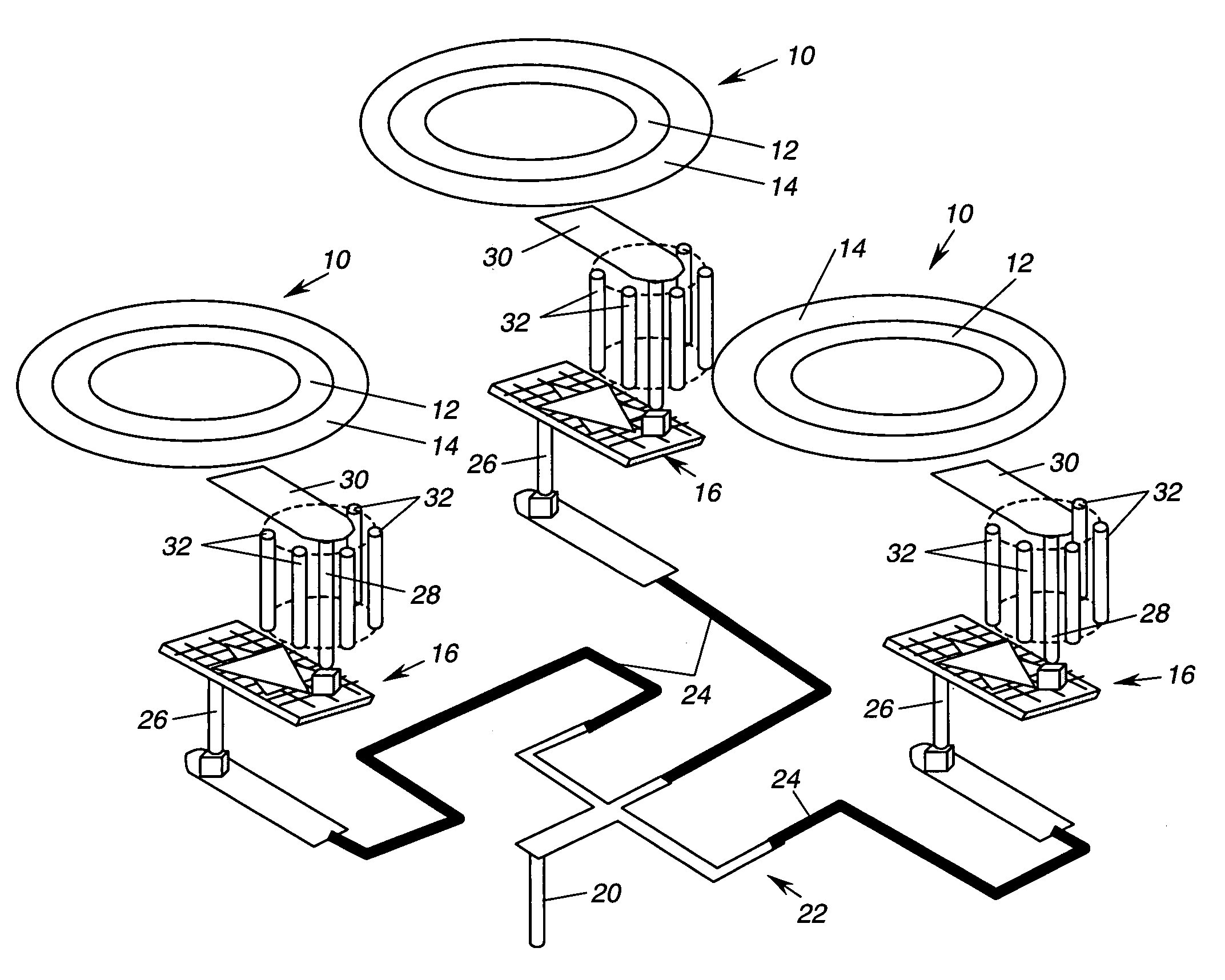
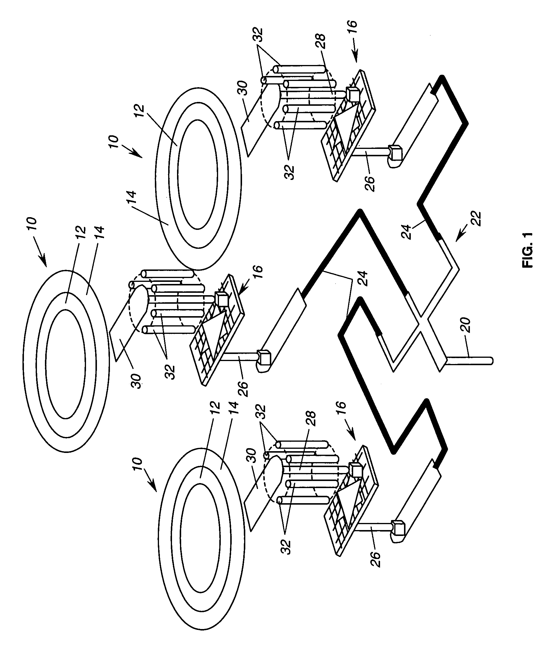
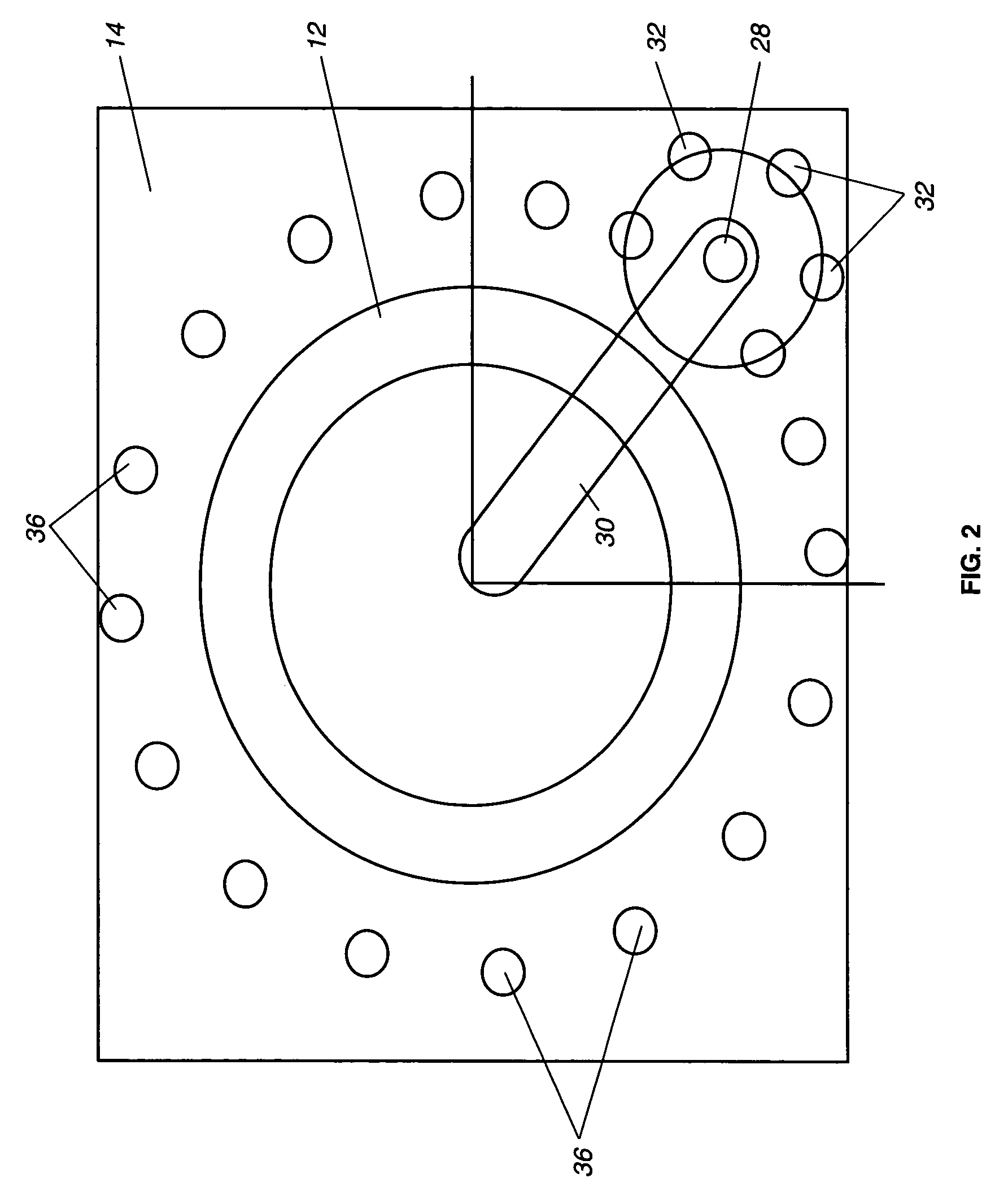
[0020]As shown in the drawings for purposes of illustration, the present invention pertains to a phased array antenna system having ring slot radiator elements, operable at millimeter-wave frequencies. Millimeter-wave frequencies are usually defined to be in the range 30–300 GHz. The present invention has important applications with a need for operation at frequencies in the vicinity of 35 GHz, and this description is consistent with a goal of operation at approximately this frequency. Prior to the present invention, arrays of ring slot radiators have been developed for operation at much lower frequencies but have not been capable of operation at millimeter-wave frequencies. One reason for this is that making a transition from a coaxial mode of transmission to a strip line mode for low profile coupling to a ring slot radiator is subject to an increasing impedance mismatch as the frequency is increased.

[0021]In accordance with one aspect of the present invention, operation at millime...


PUM


Abstract

A phased array antenna structure capable of operation at millimeter-wave frequencies and having multiple ring slot radiator elements (10). The RF feed structure for each radiator element includes a feed via (28) extending part-way through a multi-layer structure (FIG. 3) on which the radiator elements (10) are formed and a strip line feed probe (30) extending from the via (28) toward the radiator element. A key feature facilitating high-frequency operation is the inclusion of multiple mode suppressors (32) surrounding the via (28) and providing a smooth transition from a coaxial mode of RF transmission to a strip line mode of RF transmission. The feed probe (30) is tailored to provide either a narrow-band or a wideband frequency characteristic.

Description

BACKGROUND OF THE INVENTION[0001]This invention relates generally to phased array antennas and, more particularly, to phased array systems using ring slot radiator elements. Phased array antenna systems provide a convenient technique for steering antenna beams electrically. Each phased array system consists of a relatively large number of antenna elements that are separately fed with a radio-frequency (RF) signal to be transmitted. By controlling the relative phase of the RF signal in the separate antenna elements of the array, one can effectively steer a beam emanating from the array. If the array is two-dimensional, the beam may be steered about two axes. It will be understood, of course, that although such antennas are often described in terms pertaining to a transmitting antenna, the same principles also apply to steering a receiving antenna.[0002]Although such antenna systems are well known, in radar and communications systems they have typically employed conventional radiator ...

Claims


Application Information

Patent Timeline
Patent Type & Authority Patents(United States)
IPC IPC(8): H01Q13/12H01Q13/10
CPCH01Q13/106H01Q21/064H01Q21/0093H01Q21/0087
Inventor CHAN, STEVEN S.WU, TE KAOBHATTACHARYYA, ARUNRIVERA, JUANMETZEN, PHILLIP L.
Owner NORTHROP GRUMMAN SYST CORP
Learn More