Planar antenna for a wireless mesh network

Inactive Publication Date: 2006-05-30
TRILLIANT NETWORKS
View PDF40 Cites 48 Cited by
  • Summary
  • Abstract
  • Description
  • Claims
  • Application Information

AI Technical Summary

Benefits of technology

[0011]The present invention is a planar antenna that facilitates directional communication to a mesh network. The antenna is housed in a relatively small, thin, planar package that can easily be attached to a window pane or wall to enable the antenna to communicate with at least one neighboring rooftop mounted node of the mesh network. The package contains an M by N element phased array, where M and N are integers greater than one. The array

Problems solved by technology

The cost of amplitude and phase shifting circuits has prohibited

Method used


Image

  • Planar antenna for a wireless mesh network
  • Planar antenna for a wireless mesh network
  • Planar antenna for a wireless mesh network

Examples


Example

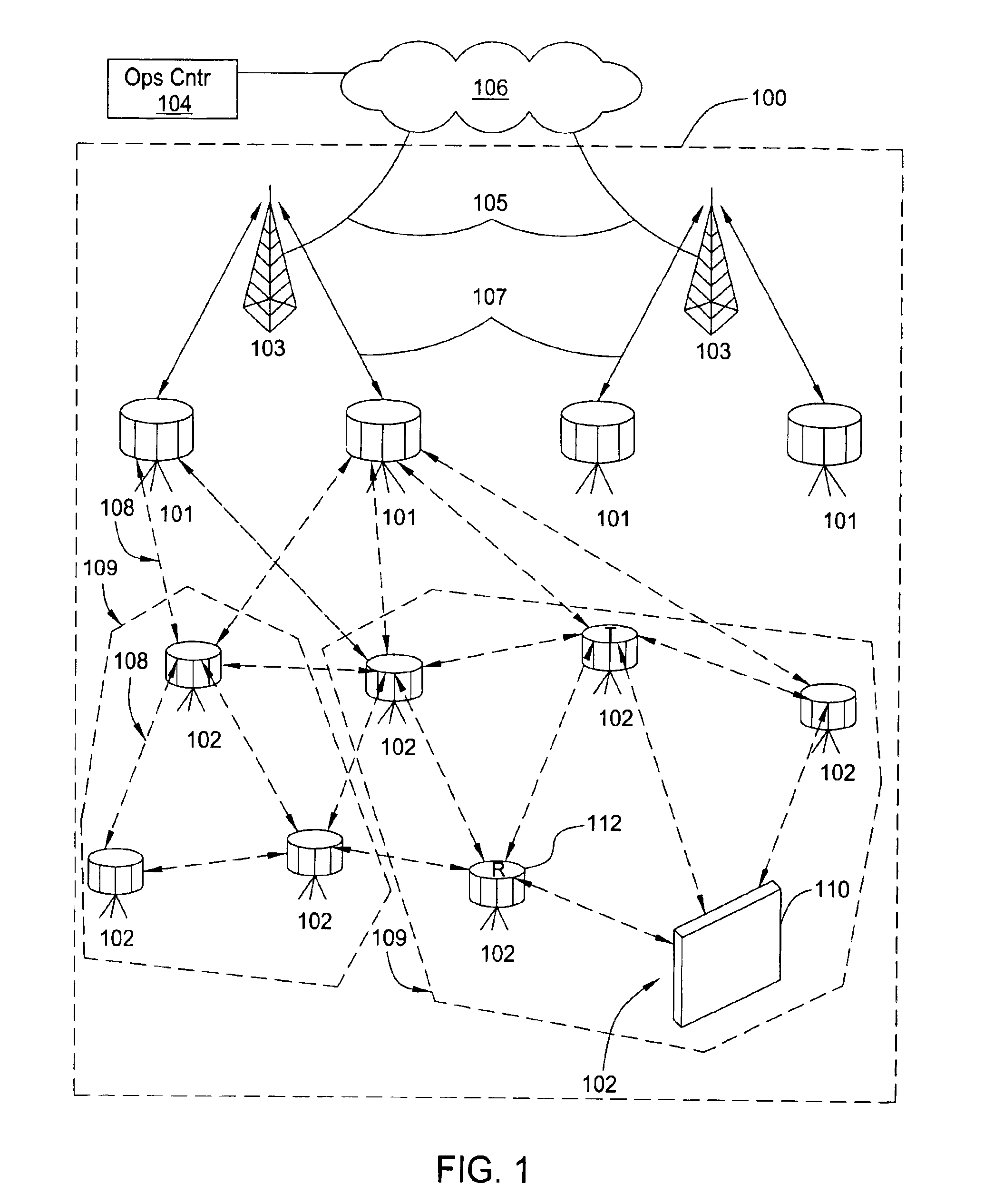
[0025]FIG. 1 is a network diagram depicting an exemplary portion of a mesh network 100 as described in commonly assigned U.S. patent application Ser. No. 10 / 122,886, filed Apr. 15, 2002 and application Ser. No. 10 / 122,762, filed Apr. 15, 2002, which are herein incorporated by reference in its entirety. Network 100 comprises network access concentrators (SNAPs) 103, network access points (NAPs) 101 and network access nodes 102. Network traffic may be routed from a network access node 102 to a neighboring network access node 102. Such a neighboring network access node 102 may route such traffic to one of its neighboring network access nodes 102 and so on until a NAP 101 or a final destination network access node 102 is reached. Notably, nodes 102 may be in communication with one another but not with any node 101 to form a private wireless network.

[0026]SNAPs 103 may be coupled to various backhauls 105, which backhauls 105 may be coupled to network 106. Network 106 may be coupled to an...


PUM


Abstract

A planar antenna that facilitates directional communication to a mesh network. The antenna is housed in a relatively small, planar package that can easily be attached to a window pane to enable the antenna to communicate with a neighboring rooftop mounted node of the mesh network. The package contains an M by N element phased array, where M and N are integers greater than one. The array is driven by microwave signals supplied from a P-angle phase shifting circuit, where P is an integer greater than one. Thus, the antenna synthesizes a single main beam and the antenna's main beam can be electrically “pointed” in one of P directions. In one embodiment of the invention, the array comprises 40 physical elements (8×5 elements) and has three selectable directions (i.e., the phase shifters provide +90, 0 and −90 degree shifts that move the beam left 45 degrees, center and right 45 degrees).

Description

BACKGROUND OF THE INVENTION[0001]1. Field of the Invention[0002]The invention relates generally to wireless networks, and more particularly to antennas for wireless networks.[0003]2. Description of the Related Art[0004]Consumer appetite for access to information continues to grow along with growth of the Internet. Corresponding to such growth, new information is added to the Internet constantly. With respect to multimedia content in particular, much of this information comes at a significant cost in bandwidth.[0005]Telephone dial-up service is being replaced with broader bandwidth systems such as satellite, digital subscriber line (DSL), and cable modem. Unfortunately, these systems are not presently available to a significant portion of the population. Moreover, acquisition and installation costs associated with these systems make them less appealing.[0006]Accordingly, wireless connectivity is on the rise. Wireless systems may be deployed more rapidly with less cost than their wire...

Claims


Application Information

Patent Timeline
IPC IPC(8): H01Q9/16H01Q1/24H01Q21/06
CPCH01Q21/065H01Q1/241H01Q21/0025H01Q3/36H01Q1/38
Inventor MERENDA, JOSEPHRICH, MARK J.
Owner TRILLIANT NETWORKS
Why Eureka
Try Eureka