
Real-time automatic loop-shaping for a disc drive servo control system

a servo control system and real-time automatic technology, applied in the direction of maintaining head carrier alignment, recording information storage, instruments, etc., can solve the problems of limiting the performance of the servo loop under changing conditions, increasing read/write errors, slowing down of read or write operations, etc., to achieve the effect of reducing vibrations, and maintaining stability in the servo loop

Inactive Publication Date: 2006-05-30
SEAGATE TECH LLC
View PDF10 Cites 25 Cited by
  • Summary
  • Abstract
  • Description
  • Claims
  • Application Information

AI Technical Summary

Benefits of technology

[0008]One embodiment relates to a disc storage system that has a servo loop for positioning a head over a disc. The servo loop includes a voice coil motor actuator that moves the head in response to a received servo control signal. A sensor, located in the head, senses servo information located on the disc and produces a servo signal therefrom. The servo signal is combined with a reference signal to produce a position error signal. A servo controller receives the position error signal and responsively produces the servo control signal. The servo controller includes a drive signal generator that receives the position error signal and responsively produces a driving energy signal. A vibration damping circuit receives the driving energy signal and responsively produces the servo control signal. A real-time adaptive loop shaping circuit, included in the servo loop, detects vibrations in the position error signal and responsively adjusts at least one par

Problems solved by technology

Misalignment of the read / write heads with respect to the tracks causes increases in read / write errors and a slowdown in read or write operations.
Using system parameters set at the time of design or manufacture limits the servo loop's performance under changing conditions.
Thus, disc drive servo control systems using fixed parameters do not function optimally under different operating conditions.
These problems worsen as track densities increase.

Method used


Image

  • Real-time automatic loop-shaping for a disc drive servo control system
  • Real-time automatic loop-shaping for a disc drive servo control system
  • Real-time automatic loop-shaping for a disc drive servo control system

Examples


case 2

)·y(t) |≦eo

Here,

K(t)=α·K(t−1), with 0<α<1  EQ. 9

When the filtered signal ef (t) is less than a specific threshold, the gain K(t) becomes smaller and smaller. Thus, if |ef(t) |≦eo, K(t) goes to zero, and no notch filter is added in the servo loop.

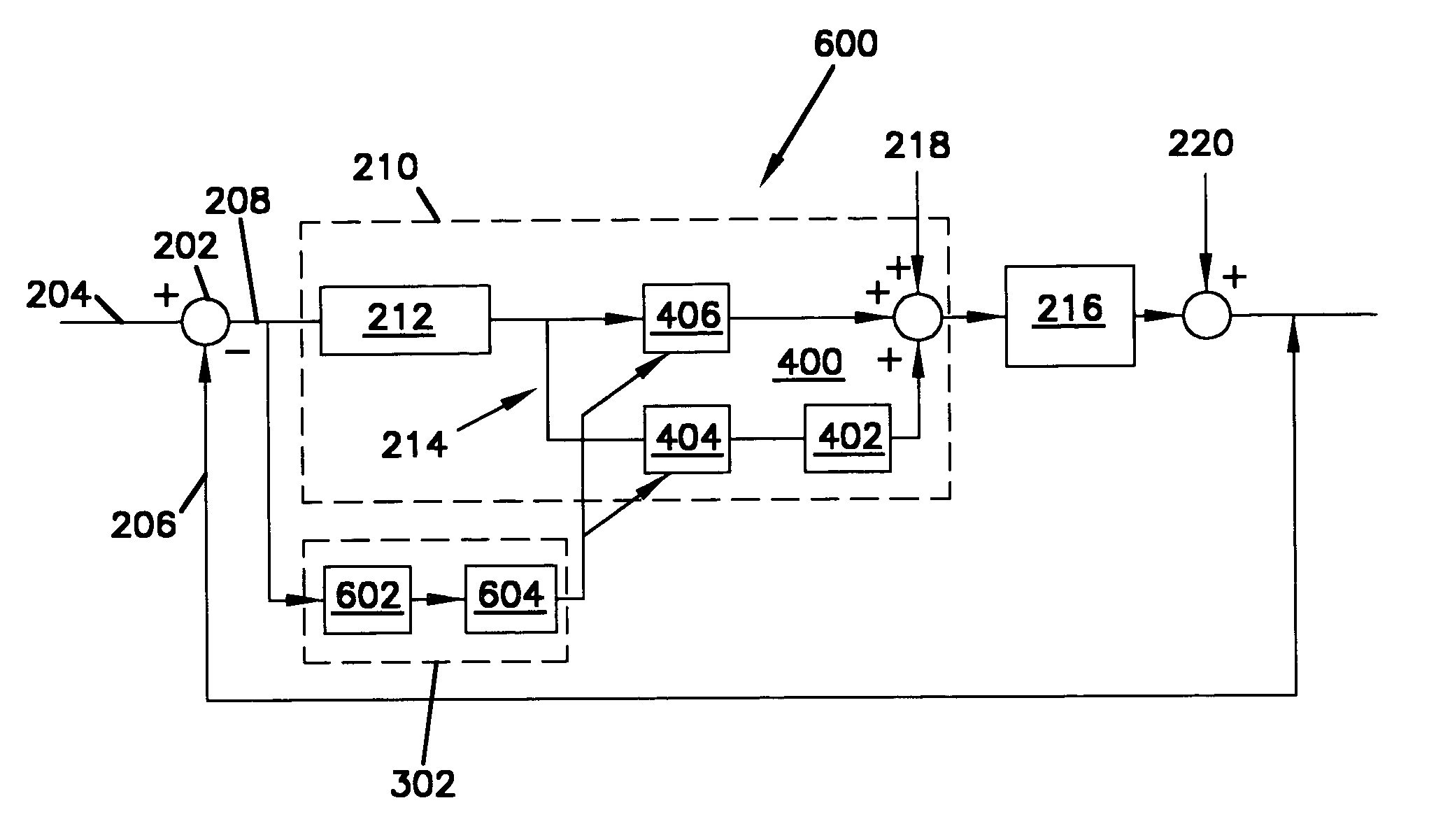
[0050]Embodiments of the present invention also provide for automatic loop shaping for NRRO cancellation. NRRO disturbances include disc flutter, bearing mode / defects and motor / disc vibration. As the track pitch of disc drives decrease, NRRO problems increase. The present embodiments provide a technique for adjusting an NRRO compensator to change dynamically according to detected NRRO disturbances.

[0051]Referring now to FIG. 9, a servo loop with a real-time adaptive loop shaping circuit used in connection with an NRRO compensator in accordance with an embodiment of the present invention is shown. The vibration damping circuit 214 in servo loop 900 includes a base NRRO compensator 904 instead of base notch filter, C (402), of servo loop 600....


PUM


Abstract

An apparatus and method for improving servo loop performance in a disc drive storage system are provided. The servo loop includes a voice coil motor actuator that moves the head in response to a received servo control signal. A sensor, located in the head, senses servo information located on the disc and produces a servo signal therefrom. The servo signal is combined with a reference signal to produce a position error signal. A servo controller receives the position error signal and responsively produces the servo control signal. The servo controller includes a drive signal generator that receives the position error signal and responsively produces a driving energy signal. A vibration damping circuit receives the driving energy signal and responsively produces the servo control signal. A real-time adaptive loop shaping circuit, included in the servo loop, detects vibrations in the position error signal and responsively adjusts at least one parameter of a transfer function of the vibration damping circuit to reduce vibrations at different frequencies in the driving energy signal.

Description

CROSS-REFERENCE TO RELATED APPLICATION[0001]The present application claims priority to U.S. Provisional Application Ser. No. 60 / 254,934, filed Dec. 12, 2000 and entitled “REAL-TIME AUTOMATIC LOOP-SHAPING OF DISC DRIVE SERVO CONTROL”.FIELD OF THE INVENTION[0002]The present invention is related to disc drives. In particular, the present invention is related to disc drive servo control systems.BACKGROUND OF THE INVENTION[0003]In a computer disc drive, data is stored on discs in concentric tracks. In disc drives with relatively high track densities, a servo feedback loop is used to maintain a head over the desired track during read or write operations. This is accomplished by utilizing prerecorded servo information either on a dedicated servo disc or on sectors that are interspersed along a disc. During track following, the servo information sensed by the head is demodulated to generate a position error signal (PES) which provides an indication of the distance between the head and the t...

Claims


Application Information

Patent Timeline
IPC IPC(8): G11B5/596G11B21/02G11B21/21
CPCG11B5/59611G11B21/21G11B5/59627
Inventor ZHANG, TAOGOMEZ, KEVIN ARTHURBI, QIANGDING, MINGZHONGKUAN, STEPHEN KOW CHIEW
Owner SEAGATE TECH LLC
Learn More