Reader/writer for magnetic memory

a magnetic memory and reader technology, applied in the field of readers/writers, can solve the problems of a large decrease in lifetime reliability, and achieve the effects of reducing the electric impedance across the capacitor, increasing frequency, and reducing the lifetime reliability

Inactive Publication Date: 2006-05-30
WESTERN DIGITAL TECH INC
View PDF6 Cites 149 Cited by
  • Summary
  • Abstract
  • Description
  • Claims
  • Application Information

AI Technical Summary

Benefits of technology

[0010]Since the head consists of metallic and dielectric layers, there are capacitances between the writer and reader leads. The electrical impedance across a capacitor decreases with increasing frequency. As a result of the capacitance, at high frequencies, a significant portion

Problems solved by technology

Therefore, only a few percent of the write current flowing through the r

Method used


Image

  • Reader/writer for magnetic memory
  • Reader/writer for magnetic memory
  • Reader/writer for magnetic memory

Examples


Embodiment Construction

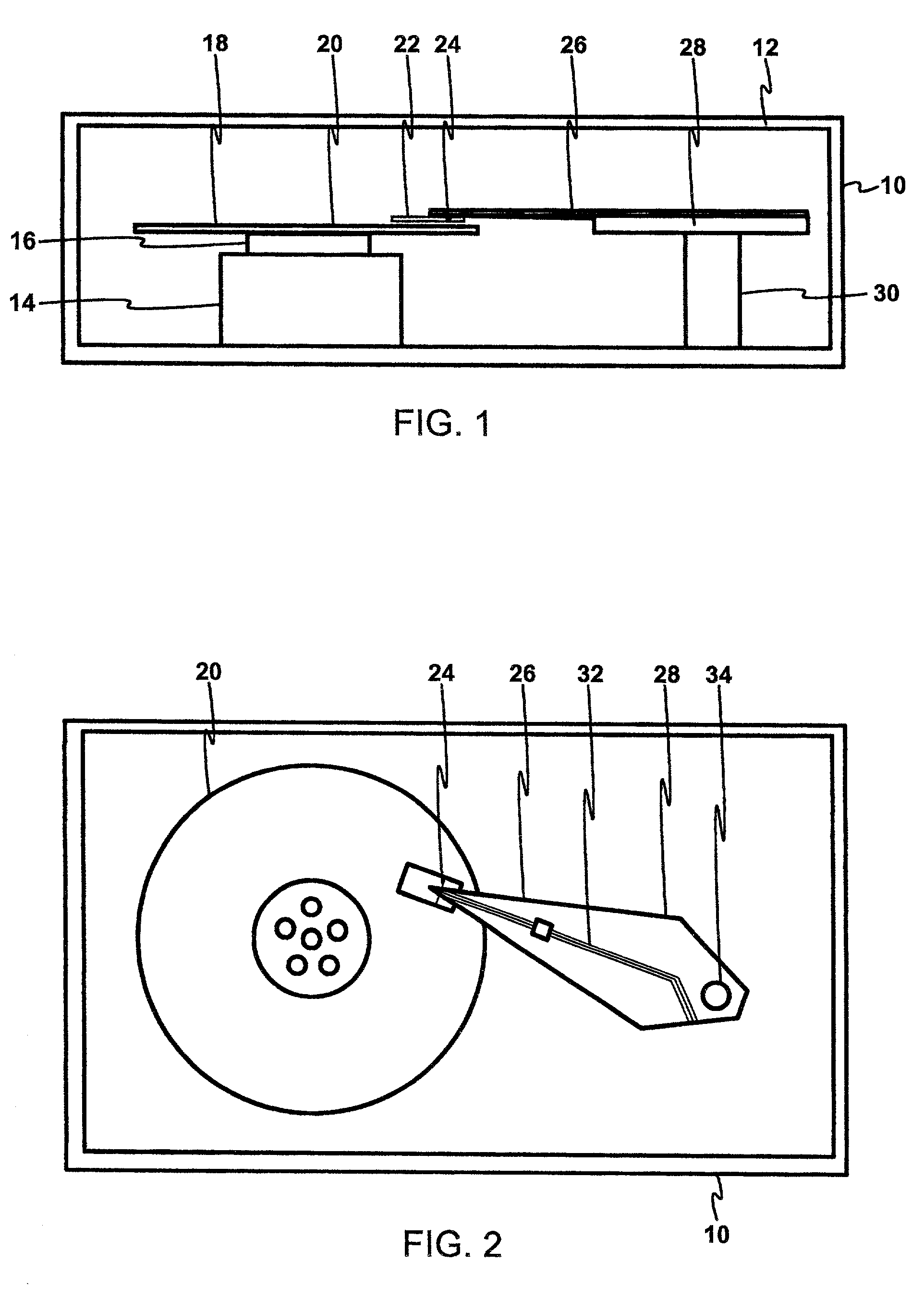
[0018]Referring now to FIG. 1, therein is shown a magnetic recording disk drive system 10. The system 10 has a housing 12 on which a disk drive motor 14 is mounted. The disk drive motor 14 is a high-speed motor having a hub 16 on which one or more magnetic recording disks, such as a magnetic recording disk 20, is mounted.

[0019]The term “horizontal” as used herein for the system 10 is defined as a plane parallel to the conventional plane or surface of the recording disk regardless of the orientation of the disk. The term as used herein for the sensor used in the system 10 is defined as a plane parallel to the surface upon which an initial layer is deposited regardless of the subsequent orientation of the surface. The term “longitudinal” as used herein is defined as parallel to the direction of movement of the disk 20. The term “vertical” refers to a direction perpendicular to the horizontal as just defined. Terms, such as “on”, “above”, “higher”, “lower”, “over”, “top”, and “under”, ...


PUM


Abstract

A method for manufacturing a reader/writer is provided having a substrate with an undercoat formed thereon. A first shield is formed over a portion of the undercoat and a pair of reader leads is formed over the first shield and undercoat. A read sensor is formed between the reader leads and a first pole/second shield is formed over the reader leads. A mid coat is formed over the undercoat and the reader leads. A second pole is formed over and in contact with the mid coat. A lead is formed over the second pole. A pedestal is formed over the reader lead and an overcoat is formed over the second pole and the lead and around the pedestal. A pad is then formed over the pedestal.

Description

TECHNICAL FIELD[0001]The present invention relates generally to reader / writers and more particularly to improving lifetime reliability in reader / writers.BACKGROUND ART[0002]A large portion of the data storage in today's computers uses magnetic media typically in the form of a disk. Data is represented to a computer by a large number of bits (ones and zeroes) and stored on disks where each bit is represented by a transition, which results in a leakage magnetic field. In order to read or write the value of any given bit, a read / write transducer is used, which includes one portion for changing or writing to the disk and another portion for detecting or reading changes in the magnetic field from transitions.[0003]In the write cycle, a large high frequency current is applied to the write coil, which magnetizes a yoke. The fringing field from a small gap in the yoke magnetizes the magnetic disk. The direction of the fringing field, and hence the magnetization of the disk switches when the...

Claims


Application Information

Patent Timeline
IPC IPC(8): G11B5/33
CPCG11B5/3143G11B5/4853G11B5/3967
Inventor SEAGLE, DAVID JOHNTHOMAS, MARK DAVIDSANKAR, SANDRAZOU, PEICORONA, CARLOS
Owner WESTERN DIGITAL TECH INC
Why Eureka
Try Eureka