Carbonaceous Nanocomposite Having Novel Structure And Fabrication Method Thereof

一种制造方法、碳纳米的技术,应用在纳米结构制造、碳纳米管、纳米碳等方向,能够解决碳纳米管没有得到广泛的应用、导电率等电特性降低、不能呈现效率、亮度等问题,达到加快氧化还原反应、电阻抗减小、粘结力良好的效果

Inactive Publication Date: 2012-05-30
INJE UNIV IND ACADEMIC COOP FOUND
View PDF3 Cites 12 Cited by
  • Summary
  • Abstract
  • Description
  • Claims
  • Application Information

AI Technical Summary

Problems solved by technology

However, the electrical characteristics such as electrical conductivity of the thin film produced by the bonding process are significantly lower than those of the direct growth due to the residual ash after sintering of the binder material as an insulator.
[0012] When carbon nanotubes are used, a phenomenon of drastic reduction in electrical characteristics due to random horizontal alignment at the time of slurry preparation occurs together with the binder problem
Due to this shortcoming, there is a serious problem that the ideal efficiency, brightness and other characteristics obtained from the theoretical calculation results cannot be presented, so carbon nanotubes have not been widely used in practice.
In addition, carbon nanomaterials have problems such as shortening the life of the device due to adhesion to the substrate and heat when the device is driven.

Method used


Image

  • Carbonaceous Nanocomposite Having Novel Structure And Fabrication Method Thereof
  • Carbonaceous Nanocomposite Having Novel Structure And Fabrication Method Thereof
  • Carbonaceous Nanocomposite Having Novel Structure And Fabrication Method Thereof

Examples


Embodiment 1

[0069] Silicon wafers were organically cleaned, and Fe catalysts were deposited with a thickness of 100 nm by radio frequency (RF) and ion sputtering. Next, the argon (Ar) gas was set to 500 sccm, and it heated for 30 minutes under the pressure of 60 torr so that the temperature might become 900 degreeC. Maintain at 900°C for 5 minutes, then set the methane gas at 25 sccm to grow carbon nanotubes for 10 minutes, then set the hydrogen gas at 500 sccm, cool for 50 minutes, and grow several layers of graphene on the silicon wafer.

Embodiment 2

[0071] Place a vial (Vial) on a hot plate and put 6ml of H in it 2 SO 4 , and then heated to 80°C. Using an electronic scale, measure 2g of K 2 S 2 o 8 and P 2 o 5 , and then slowly put in, put in 4g of graphite powder. Confirm that the color of the reactant is dark blue. After completion of the reaction, it was cooled at room temperature (25° C.) for 6 hours, and after 6 hours passed, the graphite powder was filtered with filter paper. Sprinkle deionized water on the filtered graphite powder to perform washing, and continue until the pH reaches 7.

[0072] The graphite powder that had been filtered and washed was dried overnight at room temperature (25° C.) to produce graphite oxide. Prepare a mechanical stirrer, place a Teflon beaker on top of it, add an ice box with ice and salt. Put concentrated H in a Teflon beaker 2 SO 4 (92ml) and graphite oxide (G.O).

[0073] Keep the internal temperature of the PTFE beaker below 20°C, while adding KMnO little by little ...

Embodiment 3

[0075] In order to remove the oxide groups in the graphite oxide, dip the coated substrate in the graphite oxide solution, heat it in a heating furnace at 300°C for 5 hours, and anneal to reduce oxygen to obtain graphene. Outside, carry out identically with embodiment 2.


PUM

PropertyMeasurementUnit
diameteraaaaaaaaaa
lengthaaaaaaaaaa
diameteraaaaaaaaaa

Abstract

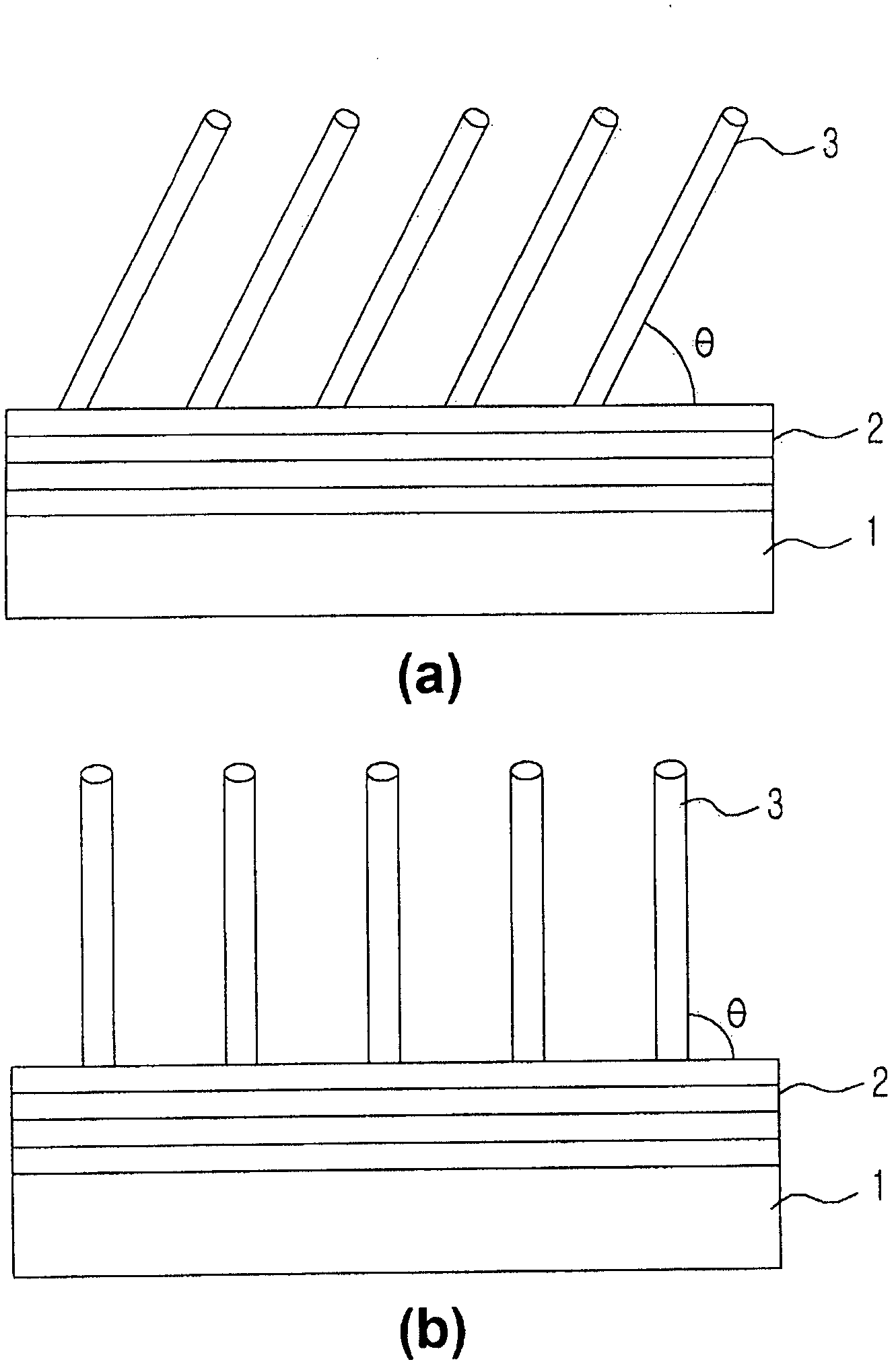
Disclosed is a carbonaceous nanocomposite, comprising: a substrate; a graphene sheet formed on a top surface of the substrate in parallel with the substrate; and a carbonaceous nano material provided at another surface of the graphene sheet, the material having an aspect ratio of 2 to 75,000 to make a predetermined angle with the graphene. The carbonaceous nanocomposite according to the present invention has excellent adhesion to the substrate and can be attached to the substrate without undergoing a pasting process. As a two-directional current flow is generated, the electrical resistance of the graphene and carbon nanotube is considerably reduced.; In addition, the carbon nanotube is configured to have a high current density through the graphene and a high specific surface area, thereby accelerating a redox reaction, and the excellent radiating property of the graphene sheet enables a speedy transfer of heat generated in the carbon nanotube to outside, thereby avoiding a degradation phenomenon of the carbon nanotube. Thus, when employed as an electrode for a battery or a field emission display, the present invention nanocomposite provides a higher current density and an extended life compared with the prior art.

Description

technical field [0001] The present invention relates to a carbon nanocomposite of a novel structure, its manufacturing method, an electrode of a battery using a carbon nanocomposite, and a field emission display device, and in particular relates to improving the bonding force with a substrate and reducing resistance A carbon nanocomposite of a novel structure capable of prolonging the life of a device, a manufacturing method thereof, an electrode of a battery using the carbon nanocomposite, and a field emission display device. Background technique [0002] In general, carbon nanotubes are often used in various fields utilizing carbon nanomaterials. For carbon nanotubes, its diameter is usually around several nm, and it is an extremely small and fine cylindrical material. In carbon nanotubes, one carbon atom combines with three other carbon atoms to form a hexagonal honeycomb pattern. Carbon nanotubes are materials that can exhibit metal conductivity or semiconductor conduc...

Claims


Application Information

Patent Timeline
Patent Type & Authority Applications(China)
IPC IPC(8): B82B3/00B82B1/00C01B31/02
CPCC01B31/0438C01B31/022B82Y40/00B82Y30/00C01B32/158C01B32/182Y10T428/24C01B32/159
Inventor 全民弦崔贤光黄叔贤金弦国
Owner INJE UNIV IND ACADEMIC COOP FOUND
Why Eureka
Try Eureka