Method and system for generating call data reports

a call data and call data technology, applied in the field of telecommunications, can solve the problems of limited flexibility, onenet and mci perspective does not, however, provide a predictable monthly bill

Inactive Publication Date: 2006-05-30
SBC TECH RESOURCES
View PDF69 Cites 7 Cited by
  • Summary
  • Abstract
  • Description
  • Claims
  • Application Information

AI Technical Summary

Benefits of technology

[0105]An advantage of the present invention is that it centralizes an enterprise's dialing pattern choices, their routing choices and their call screening configurations. When the customer subscribes to each function, the customer will experience ease of dialing, selective routing, network optimization, outbound dialing disaster recovery for carriers or chosen routes as well as centralized management of outgoing call screening.
[0106]The present invention operates in an AIN environment, including switches such as 5ESS switches manufactured by Lucent Technologies, Inc., DMS-100 switches manufactured by Nortel Networks Corporation (Nortel), AXE-10 switches manufactured by Telefonaktiebolaget LM Ericsson, or EWSD switches available from Siemens Information and Communication Networks, Inc. The 5ESS switches may utilize an AIN Release 0.1 protocol and should be equipped with Generic 5E12 (or higher) software and associated AIN SSP features. The DMS-100 switches (release NA009) may utilize an AIN Release 0.1 protocol and associated AIN SSP features. Similarly, AXE-10 switches and EWSD switches may utilize an AIN Release 0.1 protocol.
[0107]An exemplary network in which the present invention may operate is now discussed with respect to FIG. 1. FIG. 1 shows a hybrid VPN-PN network architecture, but does not show the PSTN. Although the PSTN interconnects all centrexs and PBXs, the PSTN connections are not shown. All the trunk connections shown are private trunk connections.
[0108]FIG. 1 shows locations AA and AB, which use the present invention to route originating 7+ or 9+ dialed traffic over the PSTN. Location A has a dedicated private trunk group to one of the asynchronous transfer mode (ATM) switches. This connection is necessary because, for example, location A is very large, so the aggregated traffic is cheaper to move over a private trunk group to the ATM switch and the private network than it is over the PSTN. Location A is not using the functionality of the present invention.
[0109]Locations BA, and BB employ the features of the present invention to route the originating 7+ or 9+ dialed traffic over the PSTN. FIG. 1 shows location B having a dedicated private trunk group to one of the electronic tandem network (ETN) nodes. Similar to location A, the use of a private trunk group in conjunction with the ETN node is advantageous because location B is very large and at least a portion of the traffic is less expensive to move over a private trunk group to the ETN node and the private network than it is over the PSTN. Unlike location A, however, location B employs features of the present invention because at least a portion of the traffic is cheaper to move over the PSTN than it is over a private trunk group to the ETN node and the private network.
[0110]FIG. 1 also shows locations CA and CB, which have private trunks to location C. Thus, the customer is now using features of the present invention at locations CA and CB to route the originating 7+ or 9+ dialed traffic, but private trunks are still being used. Location C has a dedicated private trunk group to an ATM switch. This is because location C is very large and at least a portion of the traffic is cheaper to move over a private trunk group to an ATM switch and the private network than it is over the PSTN.

Problems solved by technology

OneNet does not, however, provide a predictable monthly bill.
MCI Perspective does not, however, provide a predictable monthly bill.
's system is a good basic system, but provides limited flexibility and offers limited options for automatic selection of routing, centralized access to private network facilities and outgoing call screening.
's system also does not provide predictable periodic billing or centralized data collection.
's system is limited, though, to accommodating abbreviated dialing for in-network calls across more than one LATA.
's system is limited to routing calls to an information network having a predetermined access number and does not handle routine customer telephone traffic.
Currently, the virtual network systems do not provide the needed flexibility for efficiently merging a PSTN system and a private network to maximize call flow efficiency and cost control.
Rather, the systems either restrict calls to the PSTN or to private networks with little flexibility, or the systems route calls over a combination of the PSTN and private networks, based on a real time analysis of trunk and carrier availability, often resulting in duplication of effort or overuse of one of the sets of resources.
Use of only private trunk groups in this situation is overly expensive because the call traffic from individual locations is insufficient to warrant the expense of the private lines.
However, at some point, the aggregated calls from several remote locations begin to parallel one another to access the single ETN node, thus overusing the PSTN and causing excessive expense to the customer.
Conventional systems also offer limited reporting functions.
The current centrex and PBX SMDR systems, however, are independent of one another so it is not possible for the customer with both PBX and centrex SMDR records to have the data streams combined and delivered to the customer as one aggregated data stream direct from the serving PBX or network switch.
Also, each switch / PBX must be loaded with a relatively expensive SMDR package, for instructions regarding records to capture and transmit.

Method used


Image

  • Method and system for generating call data reports
  • Method and system for generating call data reports
  • Method and system for generating call data reports

Examples


Embodiment Construction

[0086]In view of the above, the present invention through one or more of its various aspects and / or embodiments is presented to accomplish one or more objectives and advantages, such as those noted below.

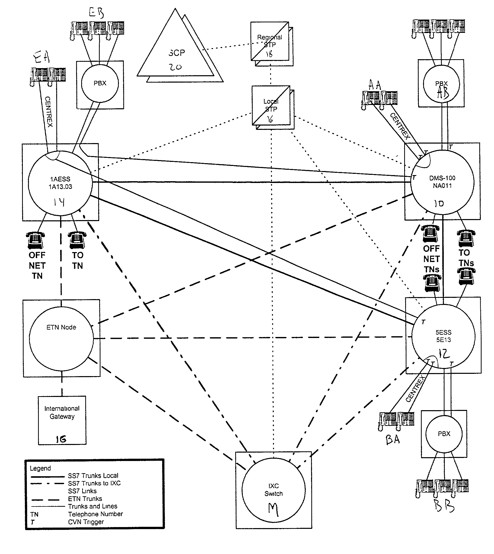
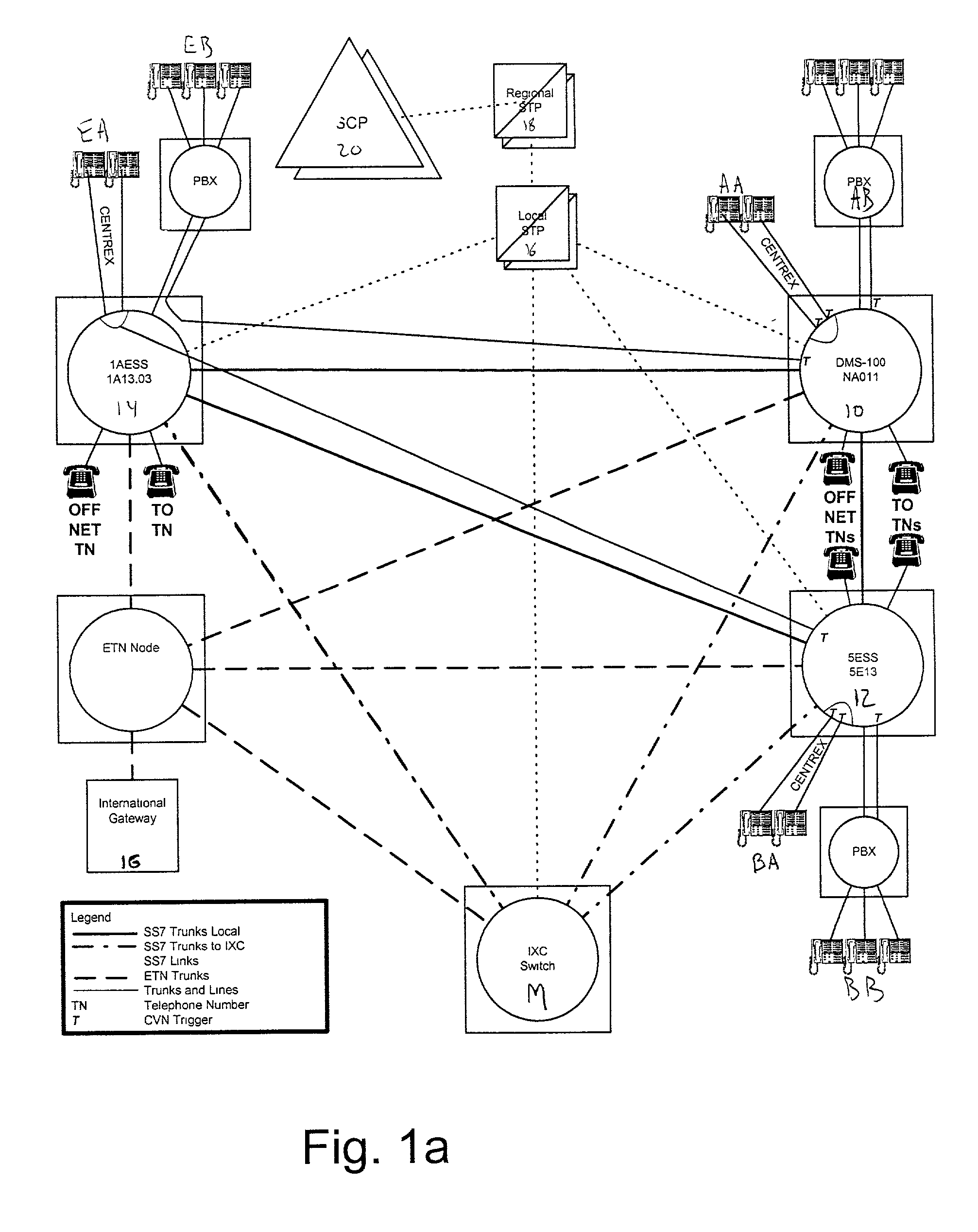
[0087]An aspect of the present invention provides a method for obtaining call data in a telecommunications system. The telecommunications system includes a service control point (SCP) and a public switched telecommunications network (PSTN), which includes at least one switch. According to the method, calling data received from the switch is sampled at the SCP and formatted as station message detail recording (SMDR) data at a front end processor. A call data report is generated from the SMDR formatted data. The sampled call data can be stored at a data distributor node or the SCP. The call data report is stored at a host processor, where it is accessible by a customer.

[0088]Another aspect of the present invention provides a method for reporting calling data to a telecommunications sy...


PUM


Abstract

A method and system for generating customer reports based on station message detail recording (SMDR) data includes a service control point (SCP) in a public switched telecommunications network (PSTN). The service control point samples calling data from multiple service switching points for calls originating from a private customer network, including centrex and PBX systems. The service control point interfaces with a front end processor and transmits the calling data. The front end processor formats the calling data into SMDR data, which is transmitted to a host central processing unit. The host generates reports regarding the SMDR calling data, the reports being accessible by a customer via a connection to a private customer network.

Description

CROSS-REFERENCE TO RELATED[0001]This application hereby incorporates by reference in their entireties the disclosures of the following applications, filed concurrently herewith: “Dialing Plan Service Including Outgoing Call Screening, Remote Tie-Line Routing, Call Data Reporting and Billing” Ser. No. 09 / 760,728, “Outgoing Call Screening” Ser. No. 09 / 760,832, “Method and System for Processing Telephone Calls via a Remote Tie-Line” Ser. No. 09 / 760,835, and “Billing for Abbreviated Dialing Plan Service” Ser. No. 09 / 760,833.BACKGROUND OF THE INVENTION[0002]1. Field of the Invention[0003]The present invention relates to the field of telecommunications. More particularly, the present invention relates to area wide central exchange service (centrex) and private branch exchange (PBX) systems.[0004]2. Acronyms[0005]The written description provided herein contains acronyms that refer to various telecommunications services, components and techniques, as well as features relating to the present...

Claims


Application Information

Patent Timeline
Patent Type & Authority Patents(United States)
IPC IPC(8): H04M7/00H04M3/22H04M7/12H04M15/00H04Q3/62
CPCH04M3/2218H04M15/00H04M15/41H04M15/44H04M15/53H04M15/58H04M15/7655H04M15/772H04M15/773H04M15/80H04M15/90H04Q3/62H04Q2213/13399H04M2215/0104H04M2215/0152H04M2215/016H04M2215/0164H04M2215/0172H04M2215/0188H04M2215/725H04M2215/7263H04M2215/7268H04Q2213/13091H04Q2213/1313H04Q2213/13141H04Q2213/13176H04Q2213/13196H04Q2213/1322H04Q2213/13222H04Q2213/13224H04Q2213/1329H04Q2213/13345H04Q2213/13383H04Q2213/13384H04Q2213/13395H04M7/12
Inventor FLEISCHER, III, HAROLD C.MORALES, LOUIS MICHAELSIMINO, JOHN E.STROUD, KENNETH ROBERT
Owner SBC TECH RESOURCES
Why Eureka
Try Eureka