Combined stage single shaft turbofan engine

a turbofan engine and single shaft technology, applied in combination engines, machines/engines, mechanical equipment, etc., can solve the problems of high fuel consumption, reduced effective range of the above-mentioned vehicles, and large fuel consumption of conventional miniature turbojet engines, and achieves low cost and simple design. , the effect of high thrust and fuel efficiency

Inactive Publication Date: 2006-06-06
HAMILTON SUNDSTRAND CORP
View PDF51 Cites 44 Cited by
  • Summary
  • Abstract
  • Description
  • Claims
  • Application Information

AI Technical Summary

Benefits of technology

[0007]As the fan bypass stage portion and the compressor stage portion rotates with the single common shaft, the compressor stage portion boosts the pressure ration and power of the core thereby providing high thrust and fuel efficiency with a relatively inexpensive and uncomplicated design.

Problems solved by technology

Although providing high thrust, conventional miniature turbojet engines typically consume relatively large quantities of fuel.
High fuel consumption reduces the effective range of the aforementioned vehicles.
Turbofan engines are relatively complex and heretofore have not been often utilized in a miniaturized form for single usage applications due to their expense.

Method used


Image

  • Combined stage single shaft turbofan engine
  • Combined stage single shaft turbofan engine
  • Combined stage single shaft turbofan engine

Examples


Embodiment Construction

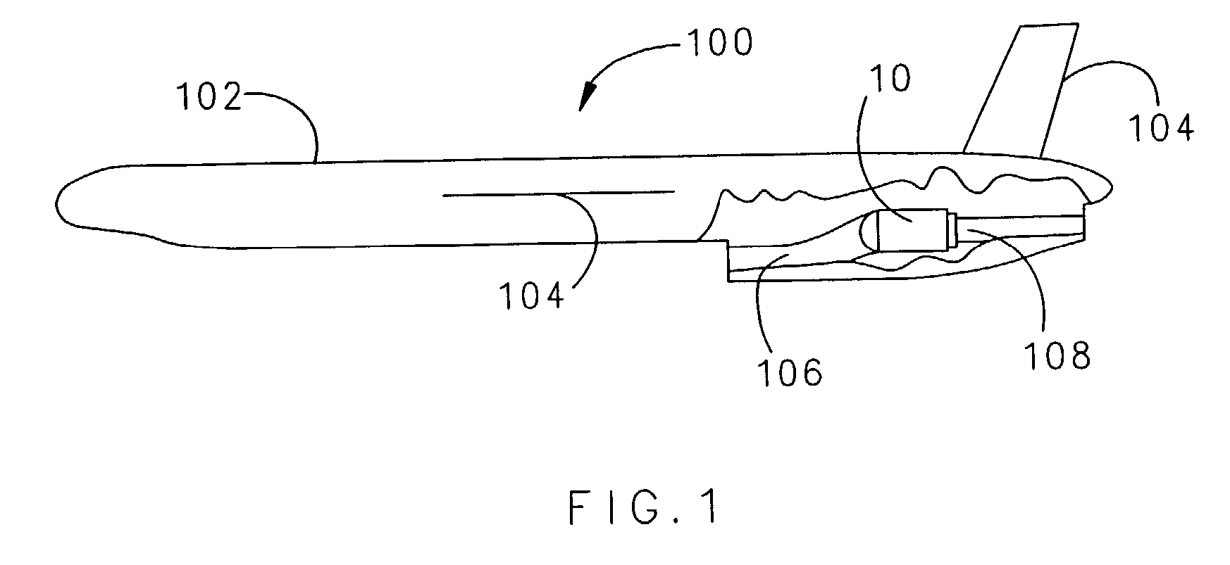
[0011]FIG. 1 illustrates a general schematic view of a vehicle 100 including a turbofan engine 10 according to the present invention. The vehicle 100 includes a body 102 and one or more aerodynamic surfaces 104. The engine 10 is coupled to, or within, the body 102. An intake 106 provides air to the turbo fan 10, and an exhaust pipe 108 is adapted to exhaust the thrust from the turbofan 10. It should be understood that multiple intakes and exhaust will benefit from the present invention. The turbofan engine of the present invention may also be used in other single usage and reusable applications such as reconnaissance drones, cruise missiles, decoys and other weapon and non-weapon applications.

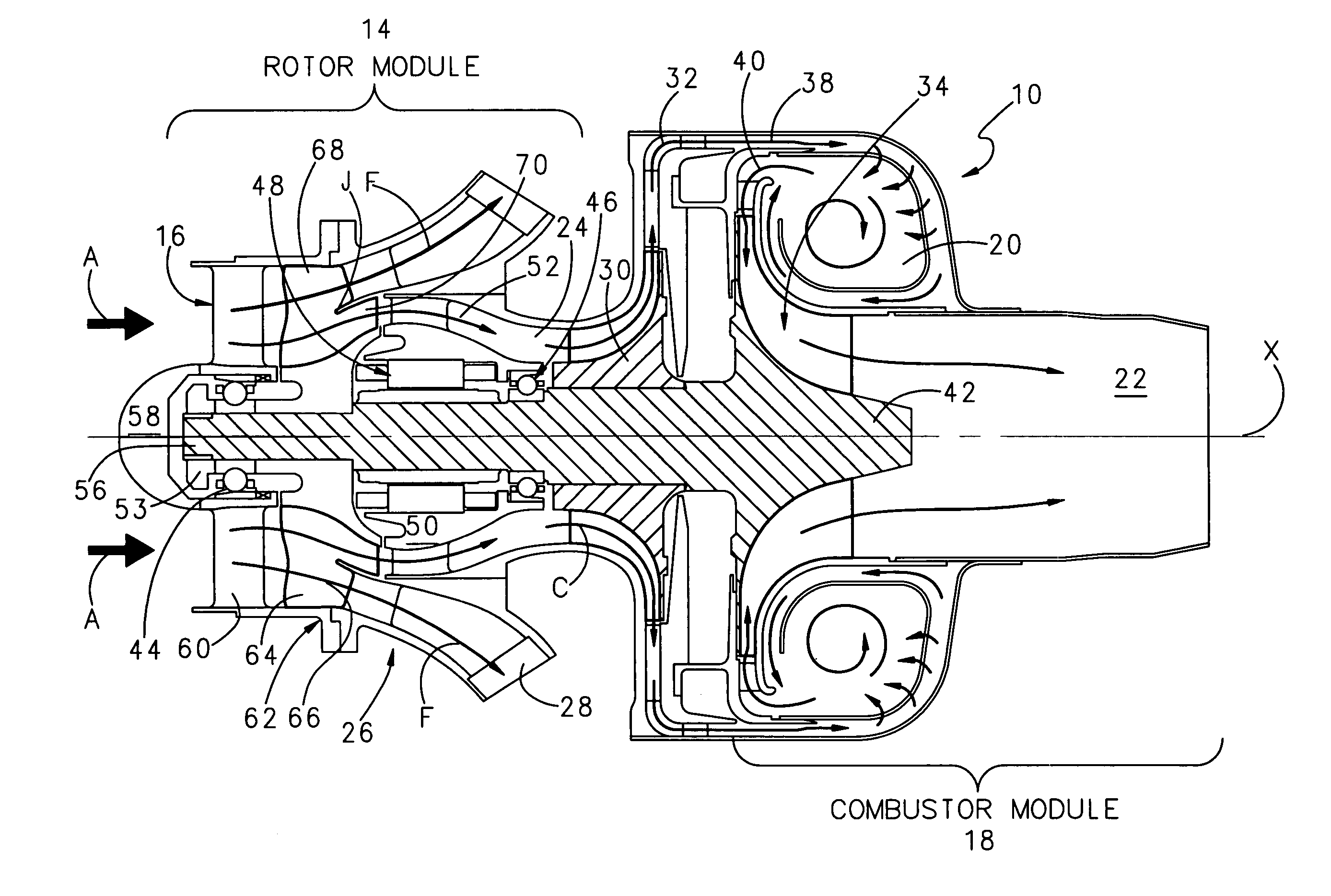
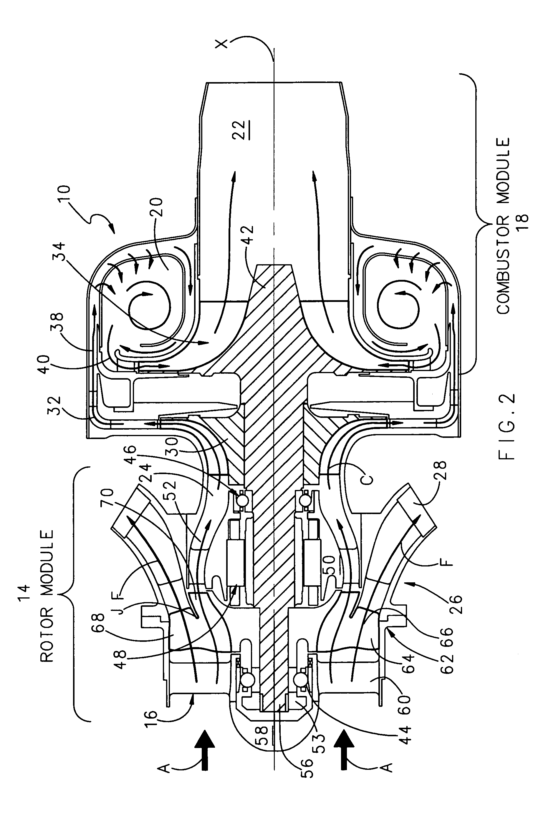
[0012]Referring to FIG. 2, the turbofan engine 10 includes a housing 12 defining a longitudinal axis X, a rotor module 14 having a forward inlet 16, and a combuster module 18 including a combustion 20 and an exhaust pipe (nozzle) 22. The turbofan 10 is defined by a core section 24 at least part...


PUM


Abstract

A turbofan engine includes a combined stage rotor mounted for common rotation with a shaft, a compressor stage, and a turbine stage. Each of the plurality of fan blades of the combined stage rotor are contiguous with a respective compressor blade. The combined stage rotor is located at a junction between a fan bypass duct and a core duct. The fan bypass stage portion includes a plurality of the fan blades which communicate incoming airflow into fan bypass airflow through the fan bypass duct. The compressor stage portion includes a plurality of the compressor blades which communicated airflow into core airflow through the core duct. The plurality of fan blades extend substantially perpendicular to the plurality of compressor blades such that the plurality of compressor blade portions extend at least partially into the core duct and preferably will include splitters for enhanced efficiency.

Description

BACKGROUND OF THE INVENTION[0001]The present invention relates to a miniature turbofan engine, and more particularly to a combined stage rotor which combines a fan and compressor into single stage.[0002]Miniature turbojet engines are often utilized in single usage applications such as reconnaissance drones, cruise missiles, decoy and other weapon applications. Although providing high thrust, conventional miniature turbojet engines typically consume relatively large quantities of fuel. High fuel consumption reduces the effective range of the aforementioned vehicles.[0003]Turbofan engines are conventionally utilized in commercial and military applications as such engines provide high thrust and fuel efficiency. Turbofan engines are relatively complex and heretofore have not been often utilized in a miniaturized form for single usage applications due to their expense.[0004]Accordingly, it is desirable to provide a turbofan engine which provides high thrust and fuel efficiency with a re...

Claims


Application Information

Patent Timeline
Patent Type & Authority Patents(United States)
IPC IPC(8): F02K3/02F01D5/02F02C3/09F02K3/06F04D25/16
CPCF01D5/022F04D25/16F02K3/06F02C3/09
Inventor JONES, ANTHONYHARRIS, MARKLYDON, PATRICKALEXANDER, ERIC
Owner HAMILTON SUNDSTRAND CORP
Why Eureka
Try Eureka