
Method and apparatus for enhancing the heat transfer efficiency of a keel cooler

a technology of heat transfer efficiency and keel cooler, which is applied in the field of keel coolers, can solve the problems of increasing back pressure and slowing down the flow of coolant, and achieve the effects of improving the flow rate, and improving the flow ra

Inactive Publication Date: 2006-06-06
R W FERNSTRUM
View PDF20 Cites 19 Cited by
  • Summary
  • Abstract
  • Description
  • Claims
  • Application Information

AI Technical Summary

Benefits of technology

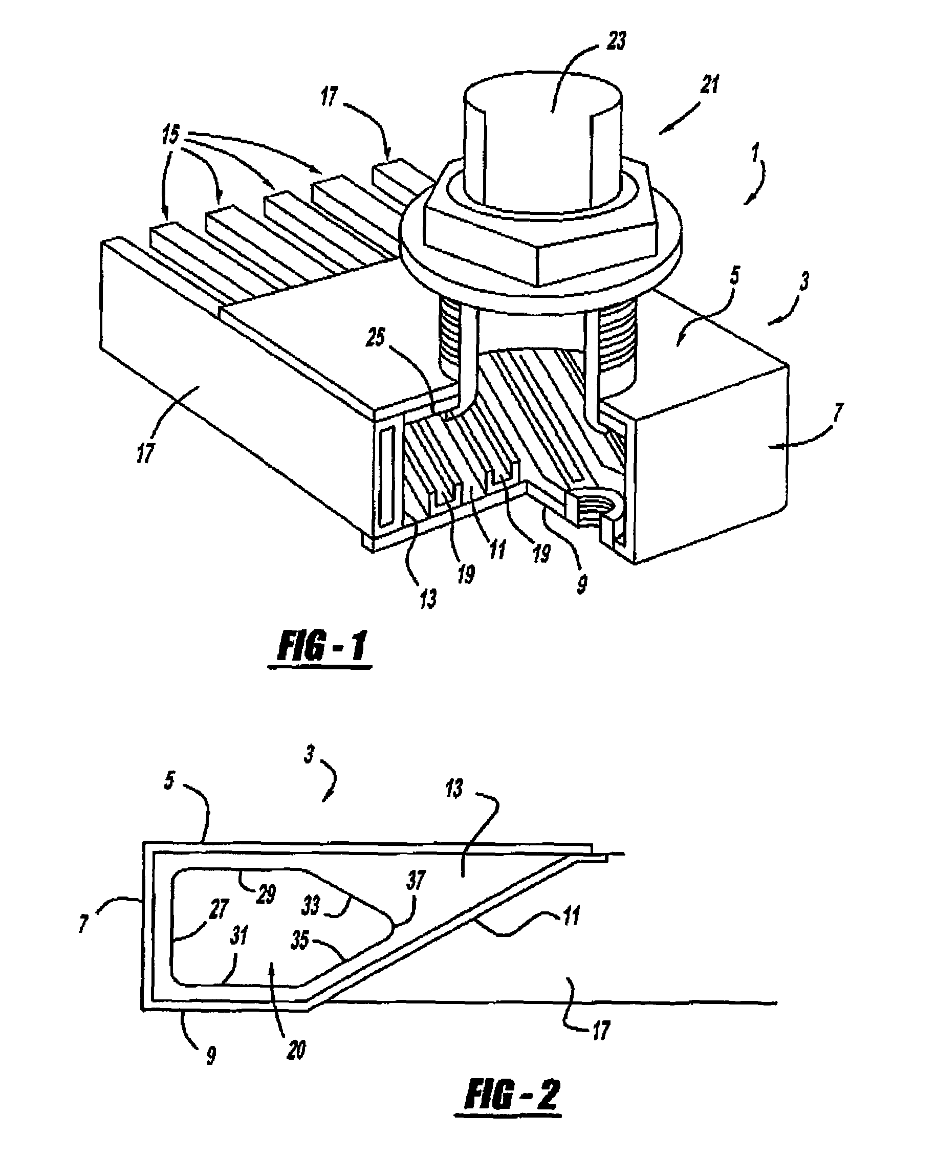
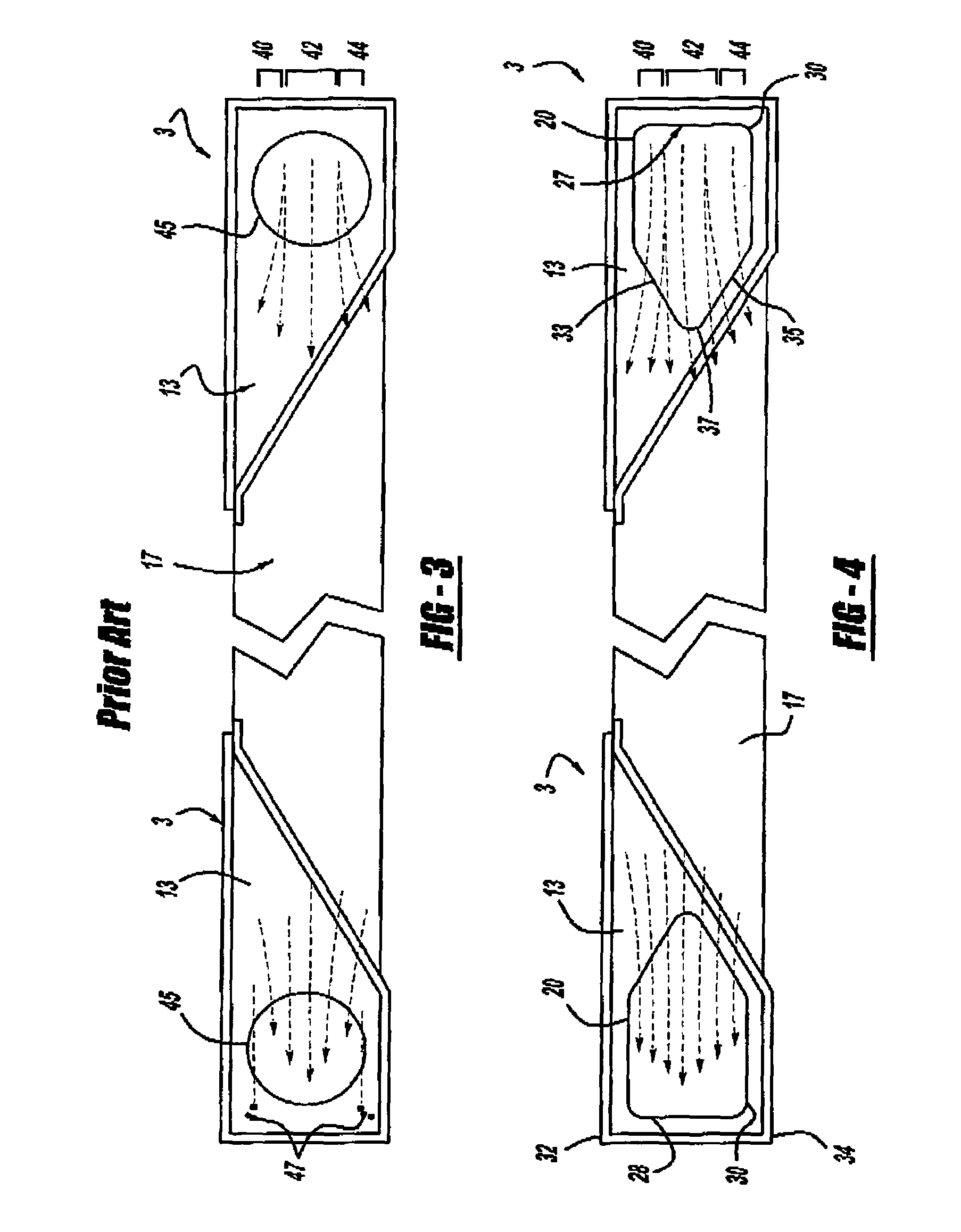
[0008]The present invention relates to a method and apparatus for improving the flow rate of coolant through side tubes that extend along the sides of a keel cooler, wherein the apertures that extend between the header and side tubes are specifically shaped and adapted to improve the flow rate therethrough. While past apertures have been circular in shape, the present invention contemplates using shapes that are designed to help increase the flow rate through the side tubes, i.e., by virtue of their unique configuration and / or orientation, which in turn can enhance the heat transfer efficiency of the cooler.
[0009]In one aspect, the apertures of the present invention are adapted to encourage the flow rate through the center of the side tubes, without necessarily limiting or restricting the flow along the top and bottom. This can be accomplished, for example, by increasing the longitudinal dimensions along the top and bottom, wherein an increase in flow, as well as an even flow distribution across the entire cross-section of the tube, can be achieved.
[0010]In another aspect, the present invention contemplates reducing dead end pocket spaces that can otherwise be formed by circular apertures. Circular apertures tend to form corners on the ends of the side walls, which can create increased back pressure that can slow the flow of coolant. Avoiding corner spaces, and therefore, dead end pockets, can help reduce back pressure, which can lead to an increase in the flow rate through the side tubes.

Problems solved by technology

Circular apertures tend to form corners on the ends of the side walls, which can create increased back pressure that can slow the flow of coolant.

Method used


Image

  • Method and apparatus for enhancing the heat transfer efficiency of a keel cooler
  • Method and apparatus for enhancing the heat transfer efficiency of a keel cooler
  • Method and apparatus for enhancing the heat transfer efficiency of a keel cooler

Examples


Embodiment Construction

[0026]FIG. 1 shows a cut-away portion of a keel cooler 1 having a header 3 on one end (the other end is not shown). The header 3 has a top wall 5, an end wall 7, a bottom wall 9, an angled weir 11, and two side walls 13 (only one is shown). The header 3 is connected to a plurality of cooling tubes, including intermediate tubes 15, and side tubes 17. The intermediate tubes 15 are preferably connected to the angled weir 11, as shown. Multiple openings 19 on the angled weir 11 communicate with intermediate tubes 15. The side tubes 17 are preferably connected along the sides of the header 3, wherein the interior walls of the side tubes can form the side walls 13. An aperture 20, such as those shown in FIGS. 2–7, is preferably provided on each side wall 13 to communicate with side tubes 17.

[0027]In one embodiment, a nozzle / nipple construction 21 preferably extends upward from top wall 5 of header 3, and is used to connect keel cooler 1 to the marine vessel, although other connecting mean...


PUM


Abstract

The invention relates to a method and apparatus for enhancing the heat transfer efficiency of a keel cooler by increasing the flow rate of coolant through the side tubes. Because the side tubes are exposed to a greater amount of fresh unhindered seawater, increasing the flow rate through the side tubes can have the effect of enhancing the overall heat transfer capability of the keel cooler. The invention relates to using apertures leading to the side tubes from the header and vice versa that are substantially arrow-shaped in design, wherein various benefits that lead to an increased flow rate are provided. The aperture is preferably symmetrically shaped so that a single die can be used to cut the aperture onto both side walls of the header.

Description

[0001]This application claims the benefit of Provisional Application No. 60 / 333,137, filed Nov. 27, 2001.FIELD OF THE INVENTION[0002]The present invention relates to the field of keel coolers, and in particular, to a method and apparatus for enchancing the heat transfer efficiency of a keel cooler by increasing the flow rate of coolant through the outer-most side tubes.BACKGROUND OF THE INVENTION[0003]Keel coolers are often used to cool mechanical equipment such as engines in a marine vessel. Keel coolers are typically located on the exterior of the marine vessel to enable cool seawater to directly pass over and contact the cooling tubes. The coolant is typically circulated through the cooling tubes and then passed through the engine which helps to cool the engine components, wherein the cycle is repeated, to enable heat to be transferred from the engine to the coolant, and in turn, to the cooling seawater.[0004]In many keel coolers, two headers or manifolds (hereinafter “headers”) ...

Claims


Application Information

Patent Timeline
IPC IPC(8): B60H3/00F28D1/00F28D1/02F28D1/04B63B3/38B63H21/38F01P3/20F28D1/053F28F9/02F28F27/02
CPCB63B3/38F01P3/207F28F9/0263F28D1/022F28D1/05366F28F9/02B63B2003/385B63B2770/00F01P2050/06B63H21/383
Inventor FERNSTRUM, TODD S.
Owner R W FERNSTRUM
Learn More