Impeller driven active heat sink

a technology of active heat sink and pump, which is applied in the direction of insulated conductors, semiconductor/solid-state device details, cables, etc., can solve the problem that the pump does not teach an open and unobstructed chamber interior for free and low-resistance hea

Inactive Publication Date: 2006-06-06
ASETEK DANMARK
View PDF10 Cites 101 Cited by
  • Summary
  • Abstract
  • Description
  • Claims
  • Application Information

AI Technical Summary

Problems solved by technology

Batchelder does not teach an open and unobstructed chamber interior for free and low resistance heat transfer flow.

Method used


Image

  • Impeller driven active heat sink
  • Impeller driven active heat sink
  • Impeller driven active heat sink

Examples


first preferred embodiment

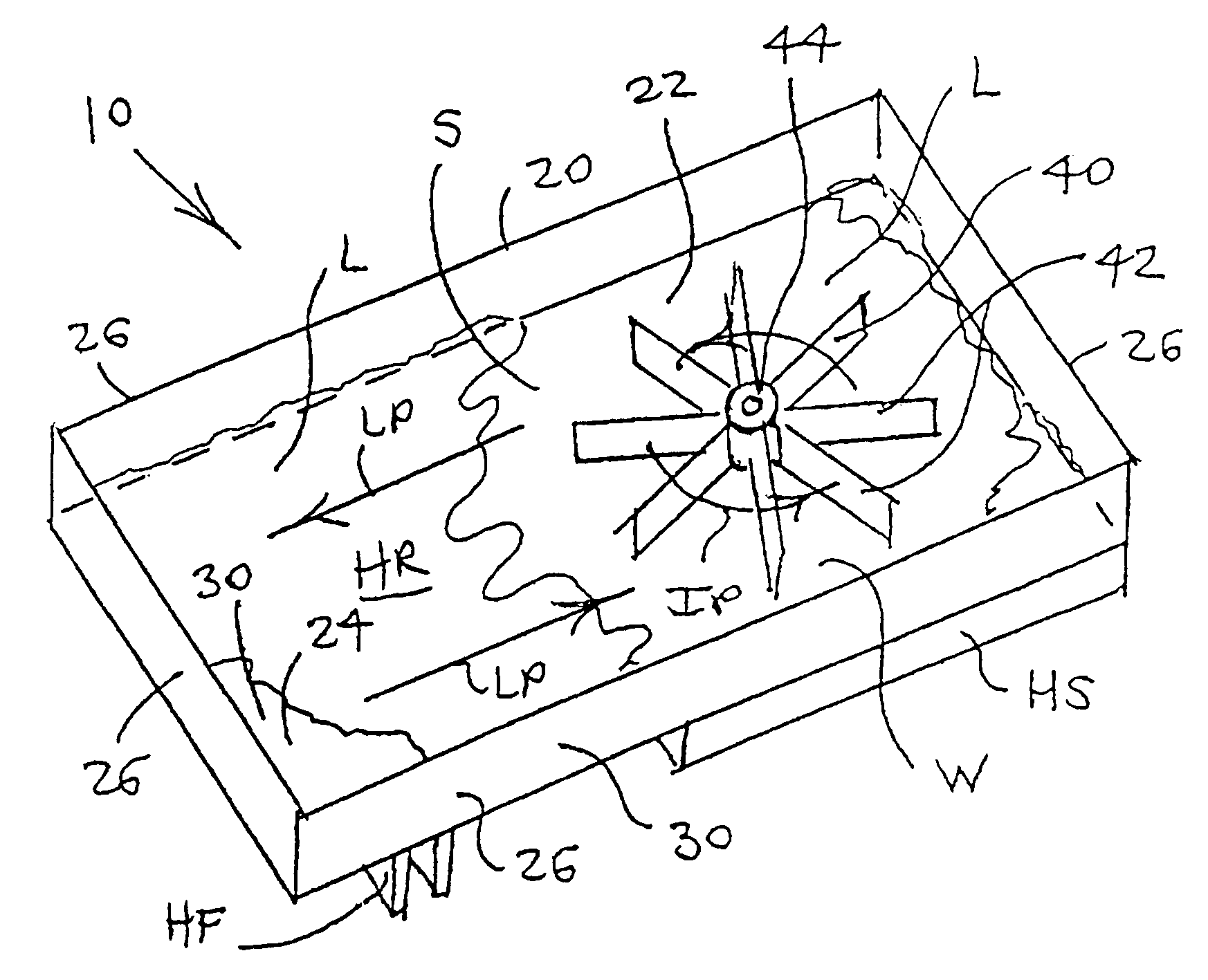
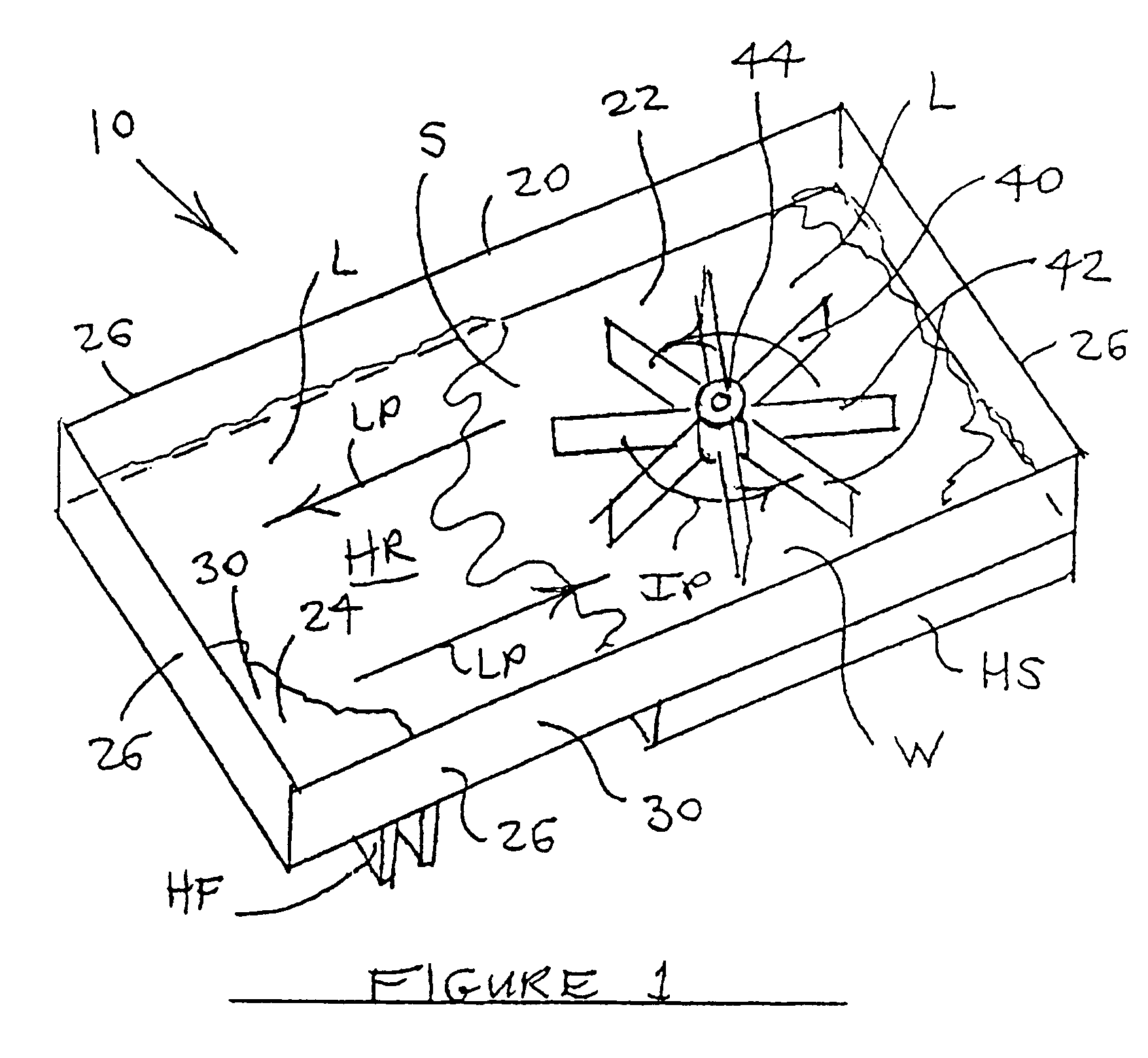
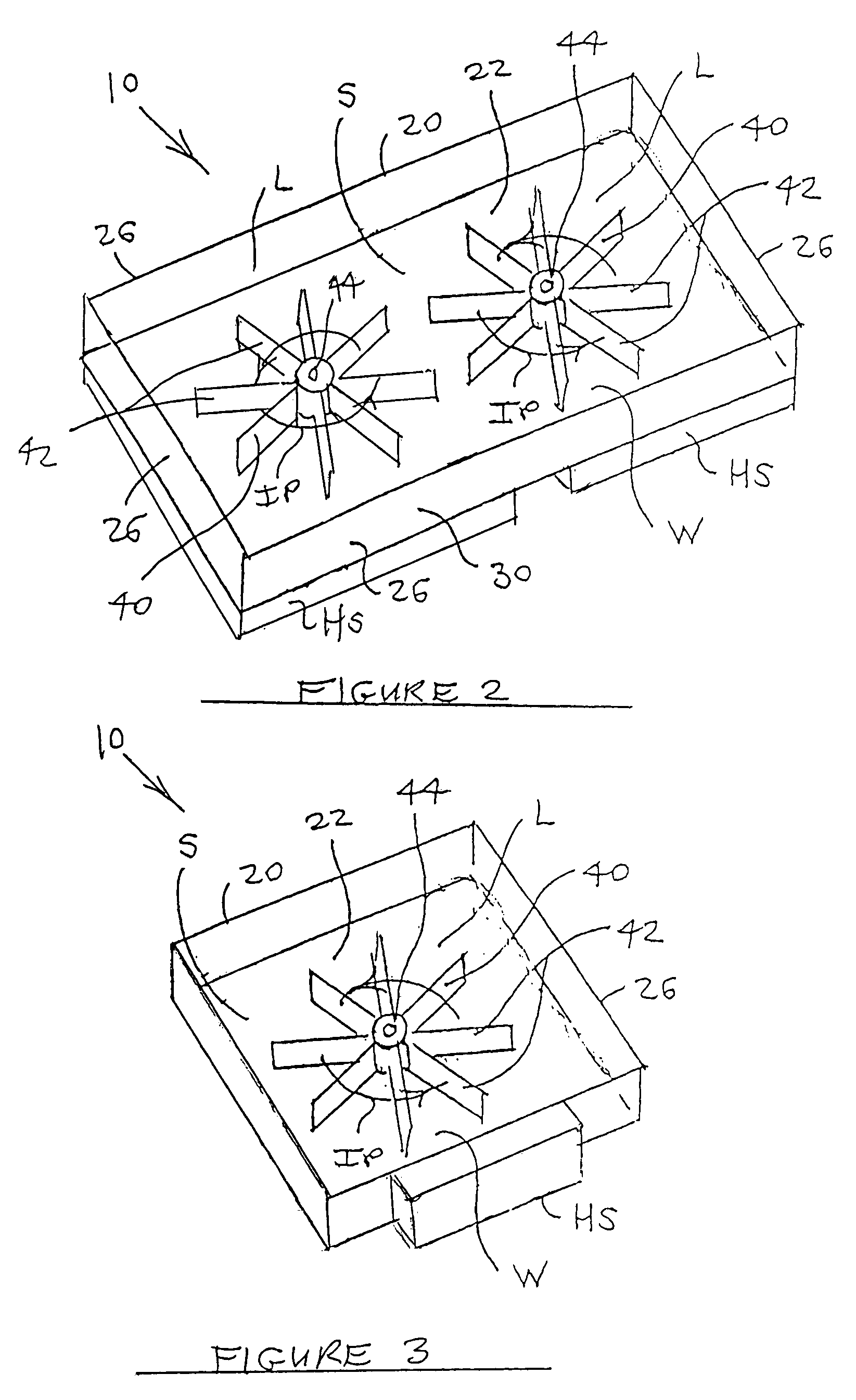
[0040]The chamber 20 of the first embodiment preferably is closed and has a chamber interior space S extending perpendicularly to the axis A of impeller 40 rotation a radial thermal spacing distance of at least the radius of the impeller 40, and preferably a radial thermal spacing distance of at least one and one fifth the radius of the given impeller 40 so that the liquid L flows to a chamber heat exchange region HR remote from the heat source HS for heat dissipation. See FIGS. 1 and 2. Heat exchange efficiency is increased with larger thermal spacing distances from the axis A, and contemplated such distances include at least one and one half, at least twice, at least three times and at least four times the radius of the given impeller 40. A thermally remote heat exchange region HR may alternatively or additionally be created by making the chamber 20 depth greater than the impeller 40 axial depth, so that the chamber second end wall 24 is spaced from the impeller 40 an axial therma...

second preferred embodiment

[0042]The chamber 20 of a second embodiment is open, having a chamber circumferential region 30 and a chamber entry port 32 and a chamber exit port 34 in the chamber circumferential region 30 so that impeller blades 42 sweep past the circumferential region 30 and draw liquid into the chamber 20 from the chamber entry port 32 and propel liquid out of the chamber 20 through the chamber exit port 34. See FIGS. 4 and 5. The circumferential chamber side wall 26 is sufficiently continuous that heat transfer liquid L propelled by the impeller blades 42 is constrained to flow along a generally circular or circumferential path about the impeller hub 44 from the entry port 32 to the exit port 34. The chamber circumferential region 30 includes the circumferential chamber side wall 26 and the peripheral portions of the chamber first end wall 22 and the chamber second end wall 24. An example of one contemplated chamber 20 configuration showing preferred entry and exit port locations is attached ...


PUM


Abstract

A heat transfer apparatus includes a heat source having a heat source maximum operating temperature; and a heat sink comprising a closed chamber having a chamber first end wall, a chamber second end wall and a circumferential chamber side wall interconnecting said chamber first end wall and said chamber second end wall, said walls defining a chamber interior space, at least one of said chamber first end wall and said chamber second end wall being a heat transfer wall, a heat transfer material retained within said chamber, and at least one impeller having an axis of impeller rotation and an impeller radius mounted within said chamber adjacent to said heat source to rotate about the axis of impeller rotation for moving the heat transfer material over said heat transfer wall and propelling said heat transfer material to a location thermally remote from said heat source for heat dissipation, wherein said chamber interior space extends perpendicular to the axis of impeller rotation a radial thermal spacing distance of at least two times the impeller radius.

Description

FILING HISTORY[0001]This application is based in part on the contents of disclosure document number 527536 filed on Mar. 10, 2003.BACKGROUND OF THE INVENTION[0002]1. Field of the Invention[0003]The present invention relates generally to the field of heat dissipation devices known as heat sinks. More specifically the present invention relates to a heat sink including a chamber having a chamber first end wall and a chamber second end wall and a circumferential chamber side wall interconnecting the chamber first and second end walls, at least one of these walls being a heat transfer wall in thermal contact with a heat source, the chamber containing a heat transfer material and an impeller having radial blades for moving the material over the heat transfer wall and propelling the material to a heat exchange region thermally remote from the heat source for heat dissipation, the chamber being configured such that the impeller(s) gather and release liquid along liquid flow paths determined...

Claims


Application Information

Patent Timeline
Patent Type & Authority Patents(United States)
IPC IPC(8): F28D15/00
CPCH01L23/427F28F2250/08H01L2924/0002H01L2924/00
Inventor ROY, SANJAY K.
Owner ASETEK DANMARK
Why Eureka
Try Eureka