Ultra low contact area end effector

a vacuum seal and end effector technology, applied in the field of vacuum gripping end effectors, can solve the problems of backside contamination and/or damage of a wafer, the difficulty of vacuum sealing a low leakage rate, and the difficulty of accurate wafer pick up and transfer, so as to eliminate or greatly minimize the effect of particulate transfer

Active Publication Date: 2006-06-06
BOOKS AUTOMATION US LLC
View PDF9 Cites 431 Cited by
  • Summary
  • Abstract
  • Description
  • Claims
  • Application Information

AI Technical Summary

Benefits of technology

[0009]One aspect of the present invention is to provide an end effector that eliminates or greatly minimizes particulate transfer to the backside of the wafer. In one embodiment, the workpiece chucks or supports include a circular knife-like edge that provides the only contact between the wafer support and the wafer.
[0010]Another aspect of the present invention is to provide an end effector that includes self-aligning vacuum chucks or supports. The workpiece supports accommodate any lack of wafer planarity and work in conjunction with distorted wafer surfaces. The supports provide an effective vacuum seal under the conditions of lack of planarity between the backside of the wafer and the vacuum supports.
[0011]Still another aspect of the present invention is to provide an end effector that includes replaceable workpiece supports. In one embodiment, each workpiece support may be readily exchanged without having to remove the end effector from the robot assembly. The workpiece supports may comprise, by way of example only, a ceramic, a plastic, or a metal. The workpiece support preferably comprises a material suited for the type of workpiece that end effector will be handling.
[0012]Another aspect of the present invention is to provide an end effector that minimizes or eliminates the amount of deformation and / or stress induced into the workpiece transferred by the end effector, with particular respect to fragile workpieces (e.g., thin wafers, SOI wafers, etc.). Even though the contact area between the workpiece support and the wafer is very small, the workpiece support provides a sufficiently large effective vacuum surface to hold the workpiece on the end effector.

Problems solved by technology

Vacuum grips often cause backside contamination and / or damage to a wafer due to: (1) scratching the backside of the wafer—particularly from hard ceramic or anodized aluminum contacts; (2) particles from the grip pad that are worn off and left on bottom of wafer; and (3) particles that fall onto the grip pad and are pressed onto bottom of wafer.
Vacuum chuck end effectors also have difficulty achieving a low leak rate vacuum seal if the wafer placed on the end effector is warped or imperfectly aligned with the end effector surfaces.
Edge grip end effectors, however, present difficulties in accurate wafer pick up and transfer.
This method also requires features to actuate the protrusions, extending and contracting them as required, which increases complexity and failure modes.
Also, these protrusions are not replaceable.
The second method involves multiple parts and potentially complex permanent assembly methods, such as those discussed above.
Edge gripping structures, however, can be expected to be relatively thick, and therefore difficult to maneuver through vertical stacking cassettes where the wafers are stored because the separation between wafers is on the order of only about 5–10 mm.
These wafers are often less than 250 microns thick and are subjected to distortion and waviness.
This presents challenges for handling thin substrates—which are conventionally not suitable for edge-grip technology end effectors.
A full 10 psi vacuum source, for example, will likely cause the wafer to warp.

Method used


Image

  • Ultra low contact area end effector
  • Ultra low contact area end effector
  • Ultra low contact area end effector

Examples


first embodiment

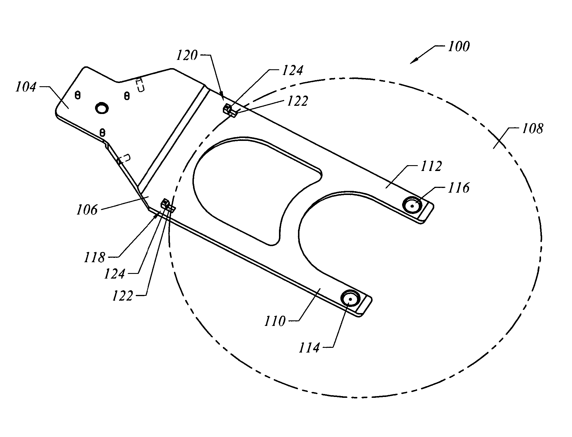
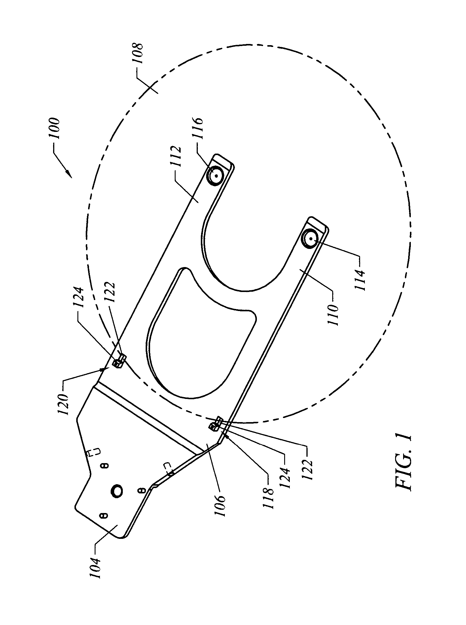
[0028]The end effector 102, in a first embodiment, includes a first end 104 adapted to secure to a wafer handling robot and a second end or platen 106 for supporting the wafer 108. The platen 106 includes a first finger 110 and a second finger 112. The first and second fingers 110, 112 are preferably spaced apart so that the first wafer support 114 and the second wafer support 116 contact different areas of the backside of the wafer 108. In this embodiment, the wafer 108 is also supported by first and second edge supports 118, 120.

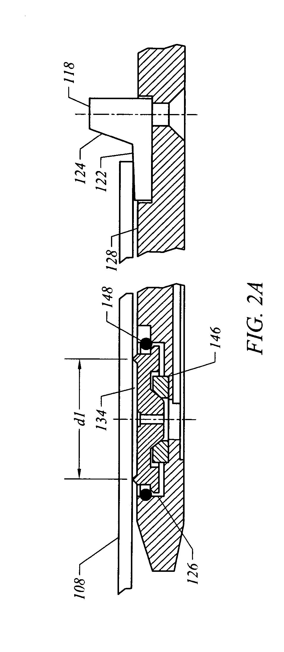
[0029]FIGS. 2A–2B illustrates that the first and second edge supports 118, 120 preferably only contact the wafer 108 along its edge or periphery. Each edge support includes a wafer support surface 122 and a backstop 124. The wafer support surface 122 is stationary and preferably comprises a low friction non-particulate generating material.

[0030]The end effector 100 includes a support retention area 126 for supporting each wafer support 114. The support ret...

second embodiment

[0047]a wafer support chuck is illustrated in FIG. 7. Instead of edge supports, the wafer support chuck 214 includes a center contact ridge 232, or other support element geometries, to support the backside of the wafer. The center contact ridge 232 is the apex of the central region 234 of the wafer support chuck 214. The central region 234 comprises a conical section, as shown in FIG. 7, yet may comprise other geometries. The chuck concept could also be used in non-robotic applications, for example, on process or metrology wafer holding stations. The chucks could be arranged in a non-planar manner to produce a curved or cylindrical wafer surface.

[0048]FIG. 8 illustrates that the contact ridge 232 is preferably a rounded surface, having a radii R. Accordingly, the contact ridge 232 and the wafer's backside 130 form a contact area d. The wafer support chuck 232 also includes an outer contact area or ridge 236. The outer contact ridge 238 preferably does not contact the wafer's backsid...


PUM


Abstract

The present invention comprises a vacuum end effector having workpiece supports that work in conjunction with distorted workpiece surfaces. In one embodiment, each workpiece support has the ability to gimbal and conform the workpiece surface in contact with an outer edge of the support. Each workpiece support preferably provides a knife-like contact edge to minimize the contact area between the support and the workpiece while still providing an effective vacuum area to hold the wafer securely on the support. In another embodiment, each workpiece support is replaceable without having to remove the end effector from the robot assembly

Description

CLAIM OF PRIORITY[0001]This application claims priority to U.S. Provisional patent application Ser. No. 60 / 486,330, entitled “Ultra Low contact Area End Effector,” which was filed on Jul. 11, 2003, and is also assigned to Applicant.FIELD OF THE INVENTION[0002]The present invention generally relates to an end effector for handling semiconductor workpieces. More particularly, the present invention relates to a vacuum gripping end effector that provides minimal contact between the workpiece supports and the backside of the workpiece.BACKGROUND OF THE INVENTION[0003]Conventional robotic vacuum chuck end effectors transfer significant particulate contamination to the backside of the wafer at areas where the chuck contacts the backside of the wafer. Vacuum grips often cause backside contamination and / or damage to a wafer due to: (1) scratching the backside of the wafer—particularly from hard ceramic or anodized aluminum contacts; (2) particles from the grip pad that are worn off and left ...

Claims


Application Information

Patent Timeline
Patent Type & Authority Patents(United States)
IPC IPC(8): A47J45/00H01L21/683H01L21/687
CPCH01L21/6838Y10S414/141H01L21/68707
Inventor BONORA, ANTHONY C.HINE, ROGER G.
Owner BOOKS AUTOMATION US LLC
Why Eureka
Try Eureka