Extended interfaced, under and around chin, head support system for resting while sitting

a support system and extended interface technology, applied in the field of portable, head support system, can solve the problems of no established practicality or utilitarian, no established practicality, and relatively high intensity of concentrated application of head weight force, and achieve the effect of easy grasping and easy movemen

Inactive Publication Date: 2006-06-06
WILLIAMS DON C
View PDF20 Cites 53 Cited by
  • Summary
  • Abstract
  • Description
  • Claims
  • Application Information

AI Technical Summary

Benefits of technology

[0012]Thus, in contrast to the relevant prior art, the present invention in its preferred embodiment is directed to a head support system for supporting the user's head in an at least generally upright disposition, while the user, for example, naps or sleeps or otherwise rests, while traveling sitting in a seat, for example, in a bus, plane, motor vehicle or the like, with the head support element interfacing with the underside of and, preferably, up and around the front and sides of the chin and from side-to-side of the chin and underneath the rest of the exposed bottom of the head back toward the top of the neck area in “face-to-face” engagement over a relatively large area with a soft but self-supporting, solid, foam, supportive material having an oblong, block shape with its extended bottom resting centrally on the upper, central chest area in “face-to-face” surface, extended engagement with the user's manubrium sterni area, and with an anchoring strap positioned, for example, around and about the back of the user's neck with means to prevent the device from being drawn into and against the neck, possibly interfering with breathing. Such an approach provides a very comfortable, reliable, full support of the user's head with a device which is very light in weight, small in size, and easily transportable.
[0013]The preferred embodiment further assists in the full interfacing by providing a combined “U”&“V” shaped, upper end portion with a centrally located, curved depression area which substantially matches the general contour of an average person's chin and surrounding facial area and the underneath area approaching the neck, namely, in front of and around and along the mental protuberance with its central cleft, preferably below the mentis, essentially forming a cup for the chin, and a generally bulbous or laterally extended, bottom portion with a bottom surface which preferably is flat and preferably has some flex or give for comfort for comfortable support on the user's strong manubrium sterni area.
[0014]Additionally, the present invention is directed to reliable anchoring or attachment subsystem always holding the device when positioned for use to the user's body, even when the user, for example, supports his / her own head with his / her neck muscles and moves the head from side-to-side, and to associated means therefor for preventing the head supporting device from being pulled inadvertently into and compressively against the throat, possibly interfering with breathing.

Problems solved by technology

However, even in this non-prior art, emergency crash system, the head supporting element is not solid and therefore not always present when located on the user but only when an emergency arises and only supports the underside of the chin and provides no on-the-sides or even side-to-side or any front support.
This relatively high intensity, concentrated application of the forces from the head's weight is relatively uncomfortable.
It is further noted that apparently there has been, no commercial success to the Palley invention and hence no established practicality or utilitarian appeal to his approach, as his patent now stands effectively abandoned due to the non-payment of its second maintenance fee.

Method used


Image

  • Extended interfaced, under and around chin, head support system for resting while sitting
  • Extended interfaced, under and around chin, head support system for resting while sitting
  • Extended interfaced, under and around chin, head support system for resting while sitting

Examples


Embodiment Construction

Listing of Reference Numbers

[0034]For ease of reference to the drawings, the drawing reference numbers are listed below.

[0035]

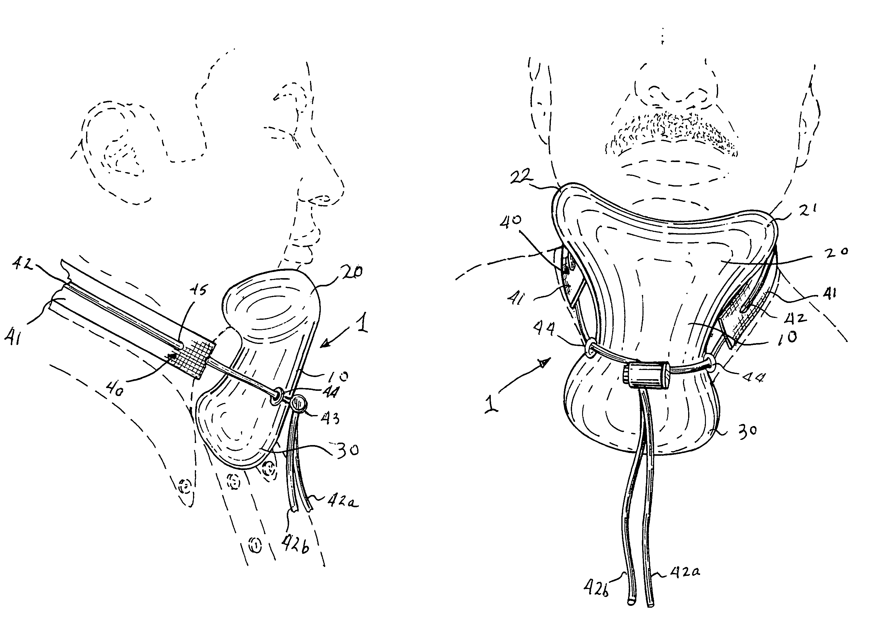
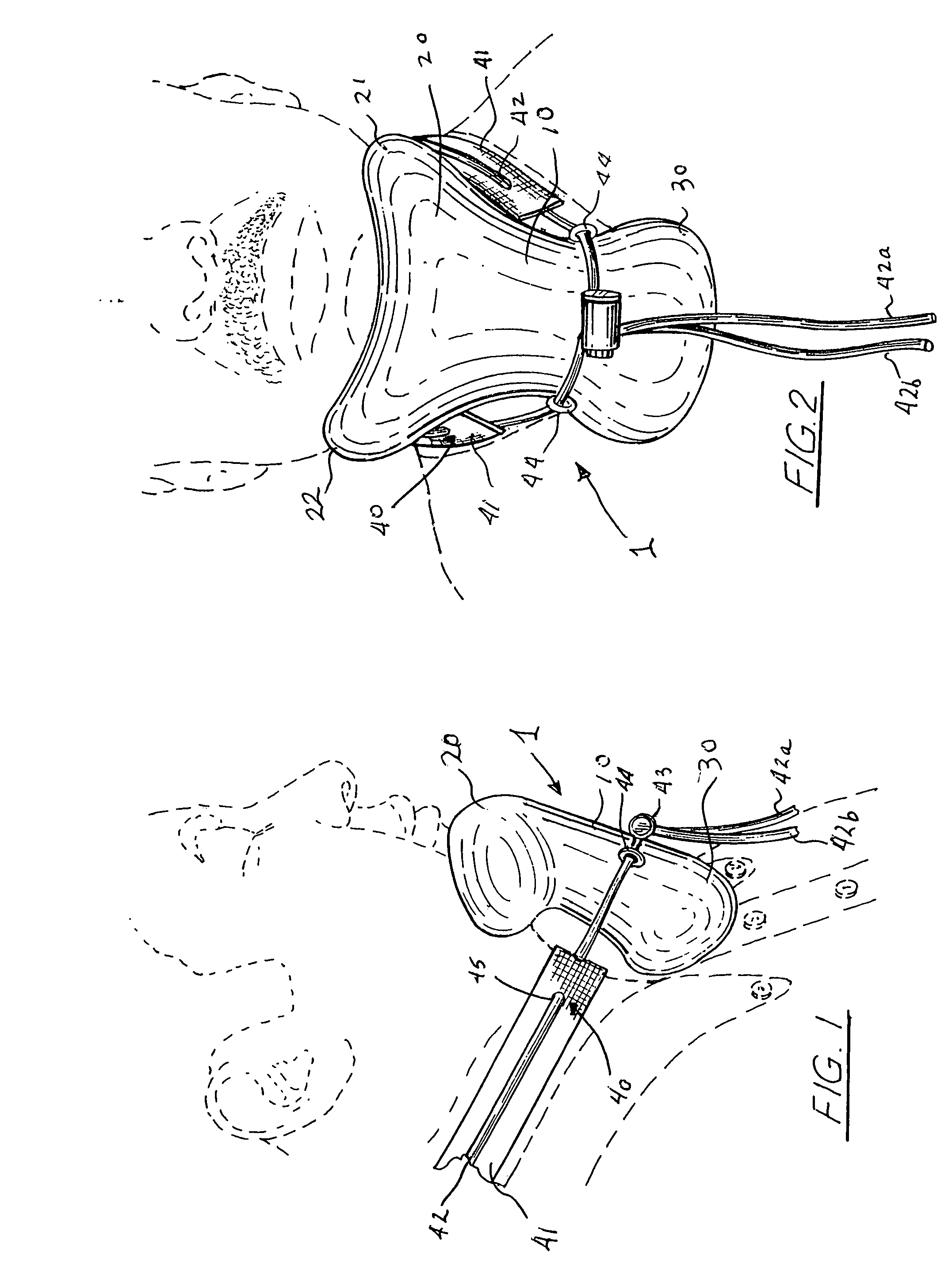
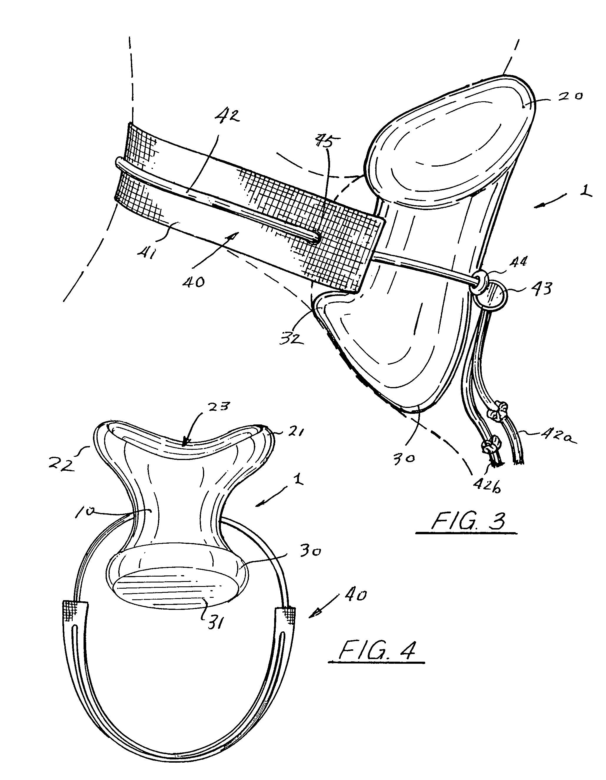
1head support element10central shank portion of head support element20top portion of head support element21left side edge of “V” shape22right side edge of “V” shape23curved interfacing depression30bottom portion of head support element31flat bottom surface40user attachment sub-system41strap of webbing material42“shoe-string” like line42aone end of string line42bother end of string line43latch43abarrel of latch43bpush button of latch44line / support-element attachment points45openings through strap section

[0036]As can be seen in the figures, the preferred embodiment of the head support system of the present invention includes a head support element 1 which has a central, reduced-cross-section, shank portion 10 flaring up and out to a top, support, chin-plus engaging portion 20 and flaring down and out to a bottom, central chest contacting foundation portion 30. ...


PUM


Abstract

A head support system for supporting the user's head in an at least generally upright disposition, while the user, for example, naps or sleeps or otherwise rests while traveling sitting in a seat. The head support element (1) interfaces with the underside of and, preferably, up and around the front of the chin, i.e., the mental proturberance with its central clef, and underneath the user's chin and from side-to-side of and along side the chin, i.e., the mandible body, in “face-to-face” surface engagement over a relatively large area, essentially forming a supportive cup for the chin, with a self-supporting but soft, solid block of molded, supportive material having an oblong shape with a reduced sized central portion (10) for hand grasping, with its angled, flat bottom (31) resting centrally on the central upper chest area of the user, preferably over and across the manubrium sterni area, with an anchoring strap (41) positioned, for example, around and about the back of the user's neck. The support element is at least generally “Y” shaped with a laterally enlarged base (30) when viewed from the front (FIG. 2). The anchoring strap subsystem (40) includes a “break-away” string-like line (42) attached to the strap with terminal ends (42a / 42b) that extend to the front loosely connected to the block and extend through and past a push-button / barrel lock (43).

Description

TECHNICAL FIELD[0001]The present invention relates to a portable, head support system for supporting the user's head in an at least generally upright disposition, while the user, for example, rests, including napping or sleeping while traveling sitting in a seat. The present invention further relates to such a head support system which interfaces with the underside of and up and around the front and sides of the chin and from side-to-side of the chin in “face-to-face” surface engagement over a relatively large chin and surrounding areas using a supportive block of solid molded foam material having an oblong shape with its bottom resting centrally on the upper, central chest of the user, with an adjustable, anchoring strap positioned, for example, around and about the back of the user's neck. Additionally, the present invention is directed to reliable anchoring or attachment subsystem holding the device to the user's body when the user, for example, supports his / her own head with the...

Claims


Application Information

Patent Timeline
Patent Type & Authority Patents(United States)
IPC IPC(8): A47C7/36
CPCB60N3/00A47C7/383
Inventor WILLIAMS, DON C.
Owner WILLIAMS DON C
Why Eureka
Try Eureka