
Compliant chain guide with multiple joints

a chain guide and chain technology, applied in the direction of belts/chains/gearrings, mechanical equipment, belts, etc., can solve the problems of vibration and force wear on the surface of the tensioner arm, etc., and achieve the effect of low cos

Active Publication Date: 2006-06-06
BORGWARNER INC
View PDF12 Cites 10 Cited by
  • Summary
  • Abstract
  • Description
  • Claims
  • Application Information

AI Technical Summary

Benefits of technology

The compliant chain guide effectively reduces wear and vibration by accommodating the chain's movement, providing a low-cost, modular solution that maintains chain tension and reduces noise and lateral motion.

Problems solved by technology

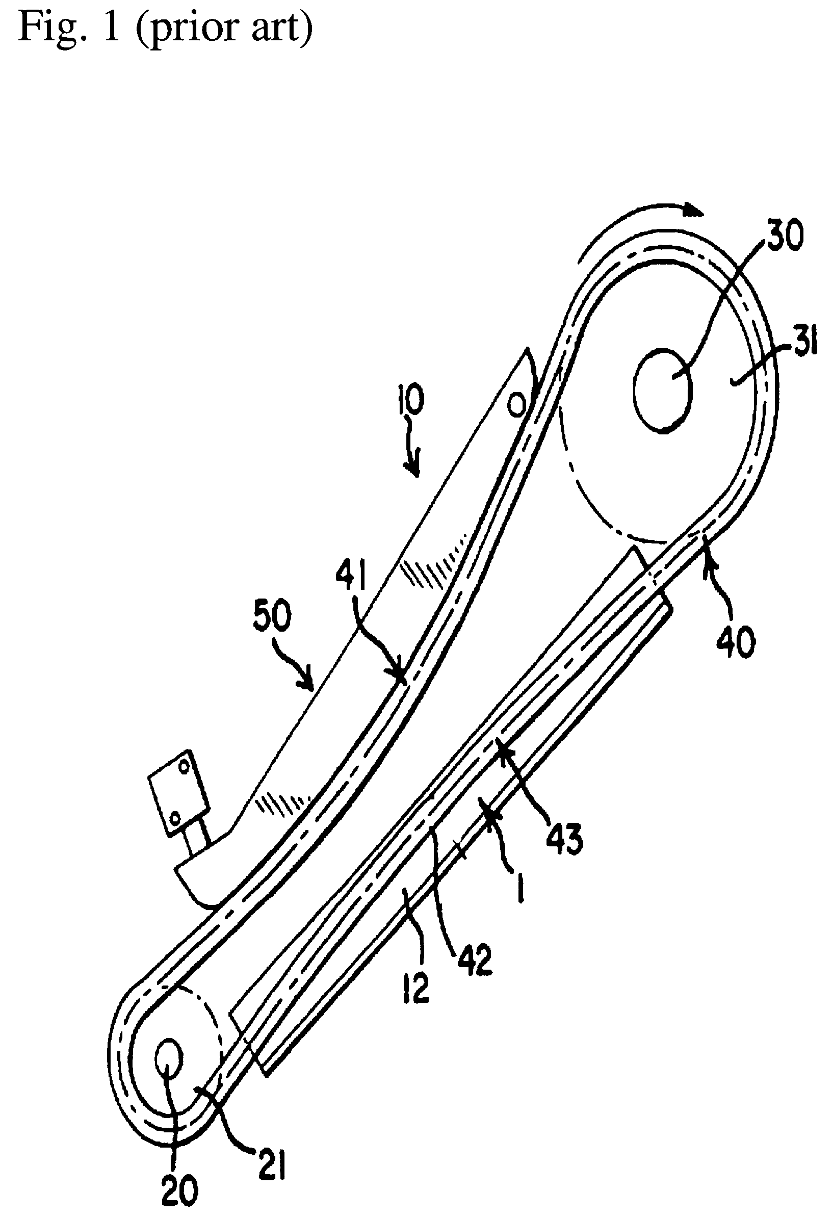
In the use of the chain tensioner on the slack side of the chain, the tensioner arm is subject to vibrations and forces from the sudden acceleration and deceleration of the engine.
Such vibration can cause wear on a tensioner arm surface.

Method used


Image

  • Compliant chain guide with multiple joints
  • Compliant chain guide with multiple joints
  • Compliant chain guide with multiple joints

Examples


Embodiment Construction

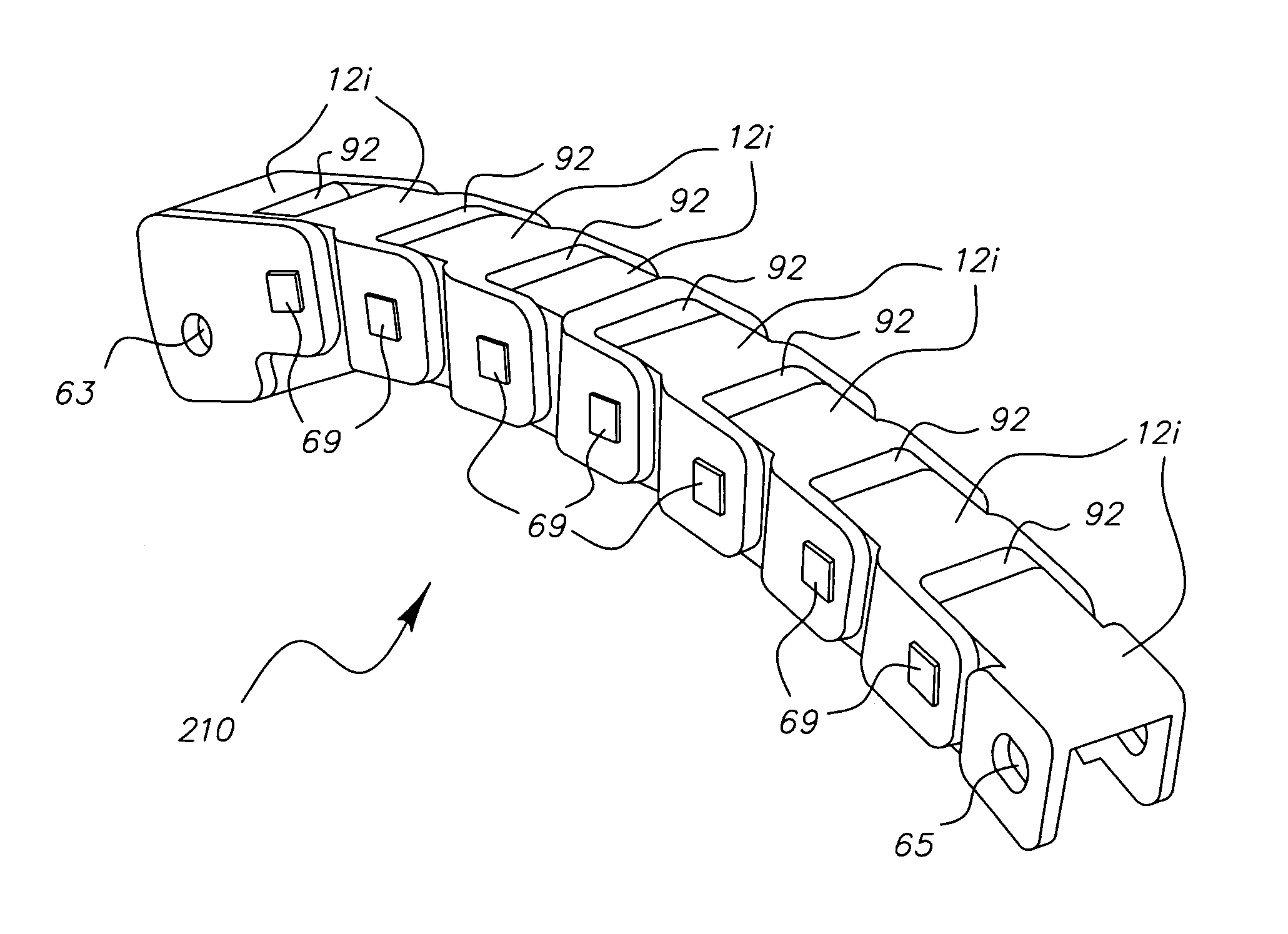
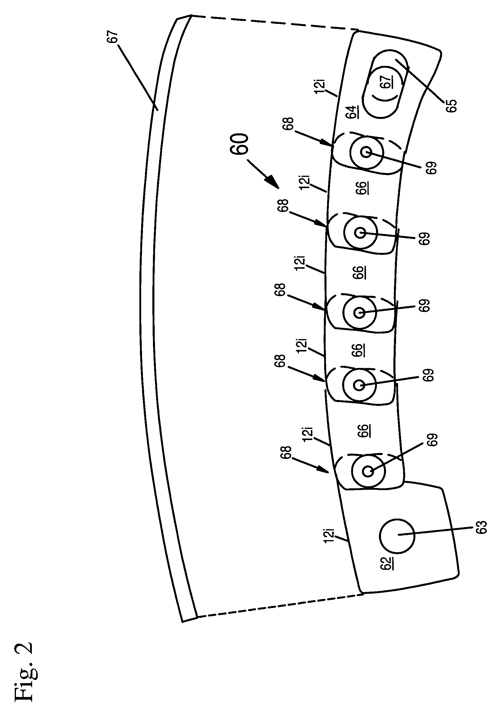
[0028]Referring to FIG. 2, a conjoined chain guide 60 of the present invention is shown. Chain guide 60 has a first end section 62 and a second end section 64. First end section 62 has an annular opening 63 for receiving a bolt (not shown) such as a shoulder bolt for allowing pivoting to occur. Second end section 64 has an elongated opening 65 which allows a bolt 67 (shown in broken lines) fastened therein to be smaller than the elongated opening 65. This way, an allowance for translational movement exists for the chain guide due to the physical shape of the elongated opening 65 thereby chain guide 60 as a whole may adjust itself somewhat given the physical shape of the elongated opening 65. Chain guide 60 may have at least one intermediate section 66. Or typically, the chain guide may have a plurality of intermediate sections 66. It is noted that the present invention includes the possibility of having only two sections conjoined together. For example, conjoined chain guide 60 may ...


PUM


Abstract

A chain guide with Multiple Joints having a plurality of sections (62, 64, 66) with each section conjoined together via a link (68) is provided. Each of the plurality of sections (62, 64, 66) has a partial upper side (12i) which forms, in part, an upper side of the chain guide. All of the partial upper side (12i) of the plurality of sections (62, 64, 66) together form the upper side of the chain guide.

Description

FIELD OF THE INVENTION[0001]This invention relates to a chain guide for guiding drive chains and more particularly, the invention pertains to compliant chain guide with multiple joints. The chain guides of the preferred embodiment of the present invention are designed for use as chain guides in engine timing systems.BACKGROUND OF THE INVENTION[0002]Conventional engine timing systems consist of a crankshaft and corresponding sprocket system which operate an engine with either single or dual overhead camshafts. The operation of a conventional engine system is based upon a chain which extends from the crankshaft to the camshaft (or camshafts) and returns to the crankshaft in an endless loop. The movement of the crankshaft and the chain causes the camshaft to rotate. Alternatively, a separate chain can drive between the two camshafts of each bank of cylinders in a dual overhead camshaft engine timing system. Examples of engine timing systems are shown in U.S. Pat. No. 5,427,580, entitle...

Claims


Application Information

Patent Timeline
Patent Type & Authority Patents(United States)
IPC IPC(8): F16H7/08F16H7/18
CPCF16H7/18F16H2007/0872
Inventor FOSTER, JEFFREYGARCIA, MARIANO S.
Owner BORGWARNER INC
Learn More