System for performing vascular anastomoses

a technology of anastomosis and system, applied in the field of system for performing anastomosis, can solve the problems of high technical and time-consuming procedure, limited number of native arterial conduits available, muscle tissue death,

Inactive Publication Date: 2006-06-06
HEARTPORT
View PDF58 Cites 51 Cited by
  • Summary
  • Abstract
  • Description
  • Claims
  • Application Information

AI Technical Summary

Problems solved by technology

When blood flow through the coronary arteries is restricted or occluded, the cardiac muscle tissue becomes deprived of adequate blood flow, which eventually results in death of the muscle tissue.
However, there is a limited number of native arterial conduits available which may be used by simply attaching one end to a blocked coronary artery.
As is the case with all other anastomoses, the surgeon must securely suture the proximal end of each conduit to the patient's aorta in order to obtain a strong, fluid tight connection, which is a highly technical and time consuming procedure.
This reduced access to the heart has increased the difficulty and time associated with forming the anastomoses between the vascular conduits and the patient's arteries, and in particular, the proximal anastomoses between the vascular conduits and the patient's aorta.
More specifically, the already highly technical procedure of suturing the vascular conduits to the aorta or other arterial blood source (as well as to the coronary arteries) is even more difficult when the surgeon is operating through a small port. e.g., an incision 3 or 4 inches in length.
As a secure, fluid tight anastomosis is highly desirable in order to provide long term patency of the conduit bypassing the blockage, minimally invasive cardiac surgery presents significant challenges for the surgeon.
The devices and methods used in conventional open-chest cardiac surgery, however, are not always usable or readily adaptable to carry out minimally invasive cardiac surgery.
As noted above, though, using suture to anastomose the respective vascular conduits is particularly difficult when performing a minimally invasive cardiac procedure.
Although stapling devices are commonly used during laparoscopic procedures to join various tissue structures, they are not designed or easily adaptable for use in minimally invasive cardiac surgery.

Method used


Image

  • System for performing vascular anastomoses
  • System for performing vascular anastomoses
  • System for performing vascular anastomoses

Examples


Embodiment Construction

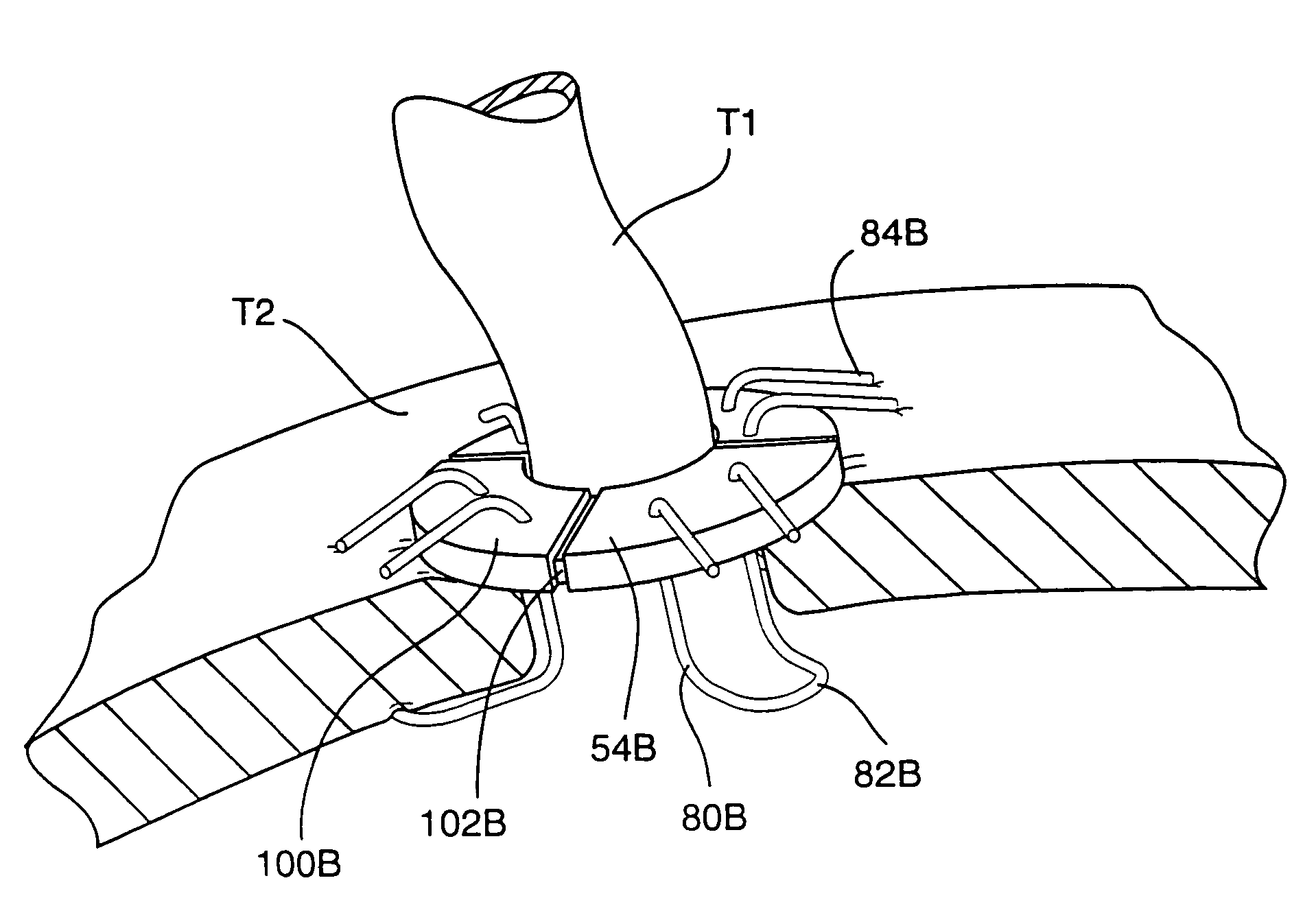
[0046]The present invention provides an anastomosis system comprising various devices and associated methods of using the devices to perform anastomosis of hollow tissue structures, which may be vascular or nonvascular structures. The devices and methods will be described in connection with a preferred application thereof, namely, coronary artery bypass grafting during which a vascular conduit, such as a vein, artery, or artificial conduit, is anastomosed to an aorta. It will be understood that the invention will find use in various other applications not specifically described herein.

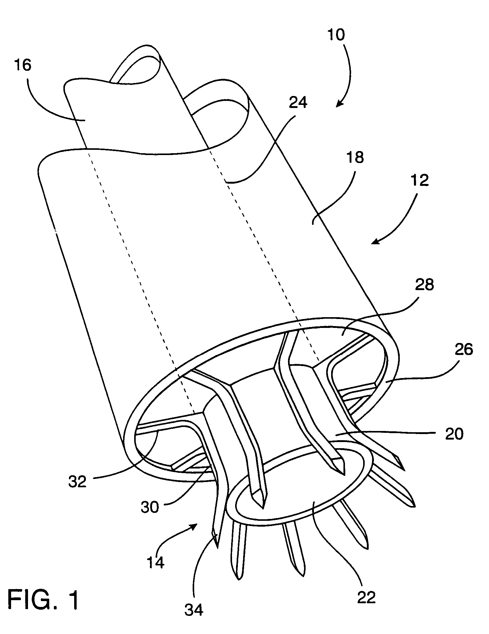
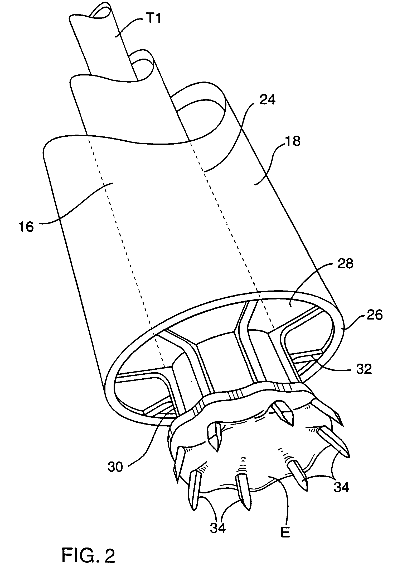
[0047]With the foregoing as background. FIG. 1 illustrates an anastomosis system indicated generally by the reference numeral 10 which comprises an applier 12 and a plurality of tissue securing members 14. The applier 12 includes first and second applier members 16, 18 which are relatively movable. In the illustrated embodiment, the member 16 is positioned within the member 18 in a sliding, telescoping...


PUM


Abstract

Systems for anastomosing a first hollow tissue structure to a second hollow tissue structure are disclosed. In an exemplary embodiment, such a system comprises at least one tissue securing member adapted to secure the first and second hollow tissue structures together, and a device for applying the tissue securing member to the tissue structures. The tissue securing member is preferably configured to pass through only one of the tissue structures, and is movable from a first configuration to a second configuration which results in a compressive force being applied to the tissue structures. The systems are particularly useful for performing anastomosis of blood vessels in heart surgery.

Description

CROSS-REFERENCE TO RELATED APPLICATIONS[0001]This application is a continuation of patent application U.S. Ser. No. 09 / 759,430, filed Jan. 12, 2001, which is a continuation of U.S. Ser. No. 09 / 227,076, filed Jan. 5, 1999, now U.S. Pat. No. 6,193,734, which is a continuation of U.S. Provisional Application Ser. No. 60 / 073,294, filed Jan. 23, 1998, which is hereby incorporated by reference.BACKGROUND OF THE INVENTION[0002]1. Field of the Invention[0003]The invention relates primarily to a system for performing an anastomosis between a first hollow tissue structure, for example, a vascular conduit such as a vein, artery or artificial blood vessel, and a second hollow tissue structure, for example, an aorta or another vascular conduit. The invention may, however, find use in other applications.[0004]2. Description of Related Art[0005]Many devices and methods have been proposed for performing an anastomosis (graft) between blood vessels. One of the most common surgical procedures carried...

Claims


Application Information

Patent Timeline
Patent Type & Authority Patents(United States)
IPC IPC(8): A61B17/08A61B17/11A61B17/122
CPCA61B17/11A61B17/122A61B2017/1142A61B2017/1135A61B2017/1107
Inventor BOLDUC, LEE R.GANNOE, JAMES R.HOULE, PHILIP R.
Owner HEARTPORT
Why Eureka
Try Eureka