Silicon steel punching orientation modifications to lower eddy current losses at the stator core end of dynamoelectric machines

a technology of dynamoelectric machines and orientation modifications, which is applied in the direction of dynamoelectric machines, magnetic circuits characterised by magnetic materials, and shape/form/construction of magnetic circuits, etc., can solve the problems of sacrificing reliability, efficiency, or performance of the machine, and prone to uprate electric machines, so as to reduce radial flux, increase the saturation level, and reduce the effect of radial flux

Inactive Publication Date: 2006-06-06
GENERAL ELECTRIC CO
View PDF1 Cites 35 Cited by
  • Summary
  • Abstract
  • Description
  • Claims
  • Application Information

AI Technical Summary

Benefits of technology

[0010]The heating caused by the eddy currents is a limiting factor in the design of large generators or electric machines. In addition, the axial fluxes add onto the normal radial fluxes in the end packages, increasing the level of saturation in the end teeth and yoke. The effect of reducing radial flux entering the first and second packages is to lower the level of saturation in these packages, enabling the axial flux to turn radially closer to the core end.
[0011]The resultant effect is to lower the axial flux densities and, therefore, the iron temperatures. Accordingly, the invention improves efficiency and allows for the up rating of large generator or electric machines by lowering eddy current losses and reducing the temperature at the core-end.
[0012]As noted above, this optimum orientation of the silicon steel laminations should preferably be used for up to the outer 20″ of each side of the generator field. The greater efficiency will result in less temperature buildup and, therefore, the entire generator field can be operated at a higher induction. The higher induction will in turn increase the energy output of the generator.
[0013]A key objective of the invention is to reduce losses and heating, especially in the generator or motor core-ends without sacrificing reliability, efficiency, and performance of the machine. This increases the potential to uprate electric machines by partially re-stacking the core-end laminations. This advancement, however, also has application in further optimizing new machines.

Problems solved by technology

The reduction of losses and heating, especially in the stator core-ends increases the potential to uprate electric machines by partially re-stacking the core-end laminations without sacrificing reliability, efficiency, or performance of the machine.

Method used


Image

  • Silicon steel punching orientation modifications to lower eddy current losses at the stator core end of dynamoelectric machines
  • Silicon steel punching orientation modifications to lower eddy current losses at the stator core end of dynamoelectric machines
  • Silicon steel punching orientation modifications to lower eddy current losses at the stator core end of dynamoelectric machines

Examples


Embodiment Construction

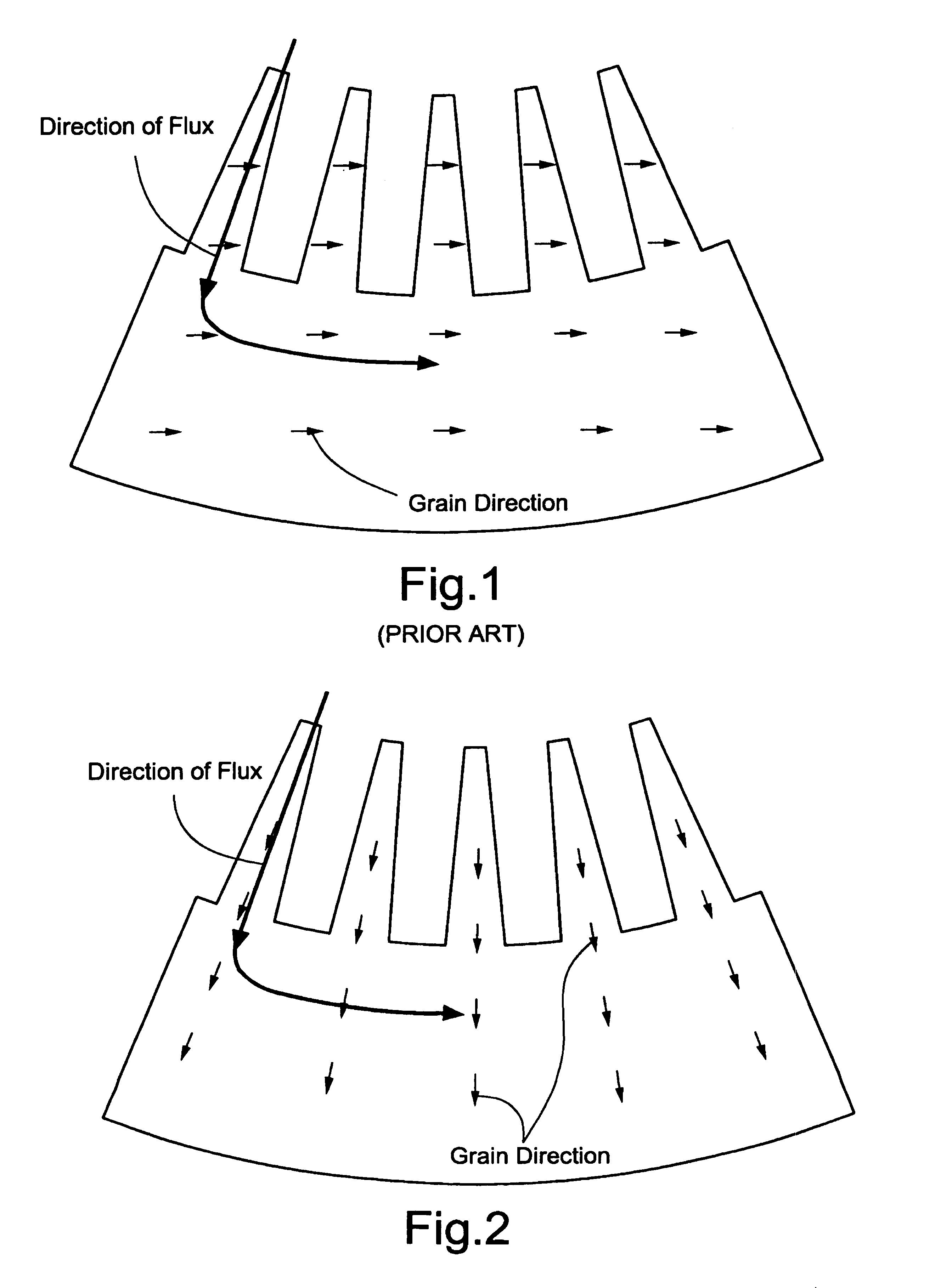
[0017]The magnetic steel used by some electric machine manufacturers is not only nonlinear, but also anisotropic. This means that there is a grain direction in the steel. Along the grain permeability is increased, whereas, across the grain permeability is decreased.

[0018]The prior art laminations are oriented such that the peripheral direction of the flux in the yoke is parallel to the preferred grain direction, as shown in FIG. 1. Magnetic losses are lowest when the flux flows parallel to the direction of grains (the easy direction).

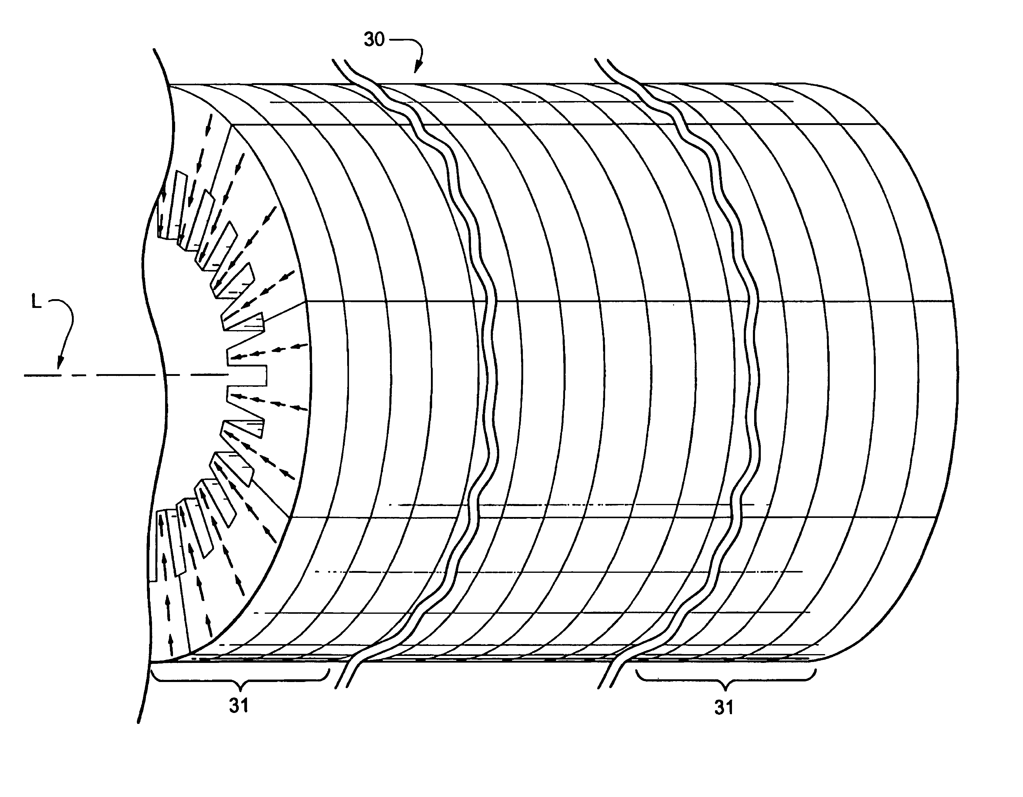
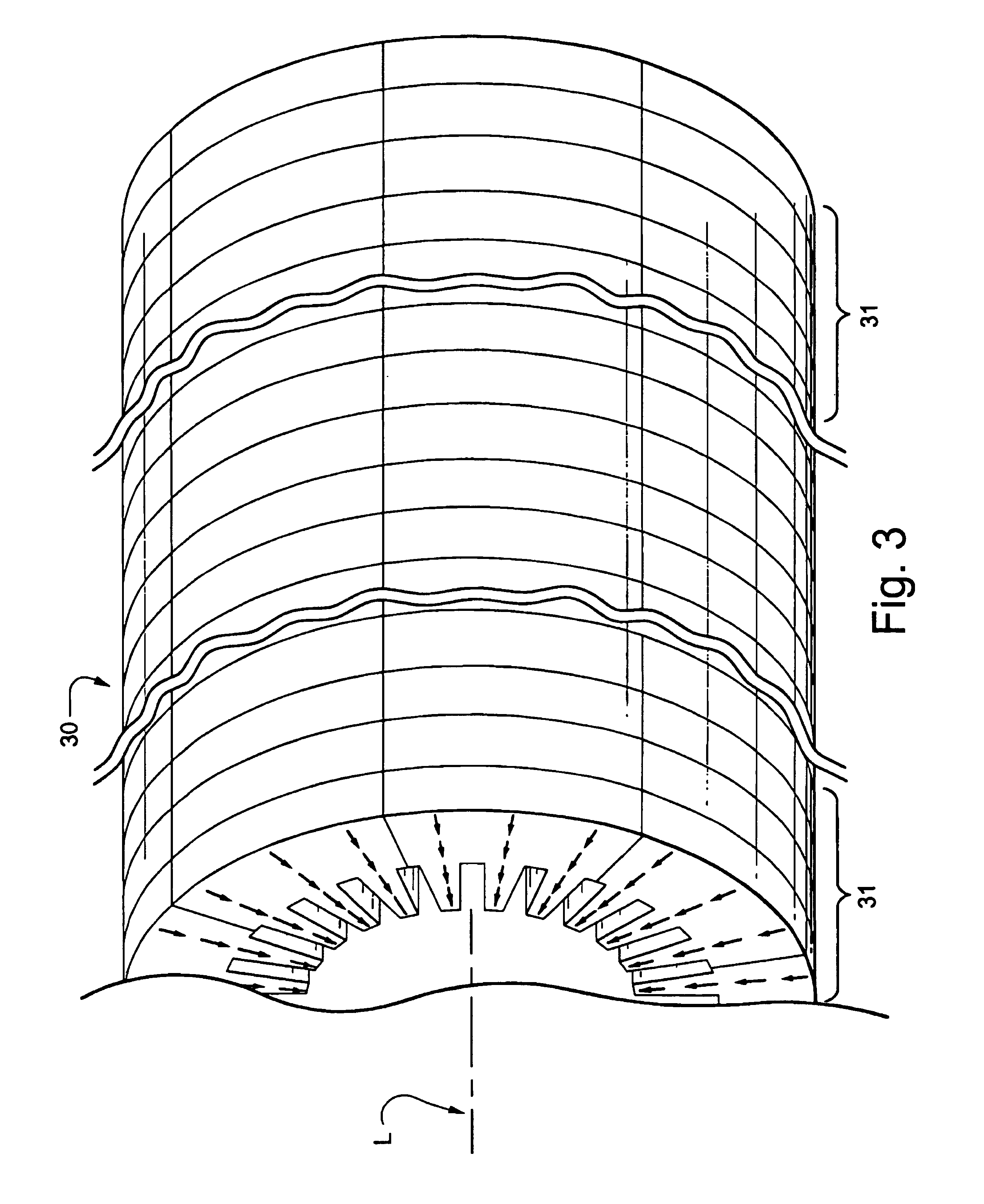
[0019]However, when the flux is perpendicular to the texture (e.g. in the teeth), the losses can be as much as three times higher as those obtained when parallel (0.68 W / lb vs. 1.7 W / lb). The core end is the area where the teeth suffer from the heating caused by impinging core-end flux.

[0020]In the invention, the use of oriented magnetic steel such that the peripheral direction of flux in the teeth is parallel to the preferred grain direction, as shown ...


PUM

PropertyMeasurementUnit
eddy current lossesaaaaaaaaaa
lengthaaaaaaaaaa
magnetic fluxaaaaaaaaaa

Abstract

The invention involves orienting the metal laminations that form a stator core end in such a way so as to reduce eddy current losses in the finger portions of the metal laminations. The metal laminations are positioned so that the grain orientation is parallel to the magnetic flux lines generated in the finger portions.

Description

FIELD OF THE INVENTION[0001]The invention is directed to reducing the electromagnetic flux normal to the stator core-end that causes eddy current losses and heating in dynamoelectric machines.BACKGROUND OF THE INVENTION[0002]There have been a number of ways proposed in the prior art for reducing this harmful electromagnetic flux. For example, increasing the air-gap length towards the end of the stator core reduces such core end flux. Reducing the relative axial length of the rotor with respect to the stator is another way to reduce the core end fringing flux. In addition, core-end stepping has been one of the commonly used techniques to modify the air-gap length in the core-ends to reduce the core end flux.[0003]The amount of core-end stepping that can be used is limited, however, by the need to support the lamination “teeth” from flexing. Loose lamination teeth can flutter and break off causing machine failure.[0004]All of these proposals for reducing the electromagnetic flux norma...

Claims


Application Information

Patent Timeline
Patent Type & Authority Patents(United States)
IPC IPC(8): H02K1/16H02K1/02
CPCH02K1/16H02K1/02
Inventor BREZNAK, JEFFREY M.SALEM, SAMEH RAMADAN
Owner GENERAL ELECTRIC CO
Why Eureka
Try Eureka