LED array implementation

a technology of led arrays and arrays, applied in the field of led arrays, can solve the problems of increasing the overall bill of materials, inefficient arrangement, increasing etc., and achieve the effect of reducing the number of inputs required to control the array

Inactive Publication Date: 2006-06-06
LANTIQ BET GMBH & CO KG
View PDF2 Cites 25 Cited by
  • Summary
  • Abstract
  • Description
  • Claims
  • Application Information

AI Technical Summary

Benefits of technology

[0006]The invention relates generally to the implementation of LED arrays. In particular, the invention relates to an improved implementation for an LED array wherein the number of inputs required to control the array is reduced.

Problems solved by technology

This arrangement can prove to be inefficient when the LED matrix has a large number of rows and columns.
As evident from above, the conventional arrangement is not conducive to miniaturization of chip size and presents a problem particularly in portable electronic devices such as mobile phones, radios and chipcards.
This approach, however, has the disadvantage of increasing the overall Bill of Materials (BOM) as there is a need for an external decoder and decoding switches for each group of rows / columns.

Method used


Image

  • LED array implementation
  • LED array implementation
  • LED array implementation

Examples


Embodiment Construction

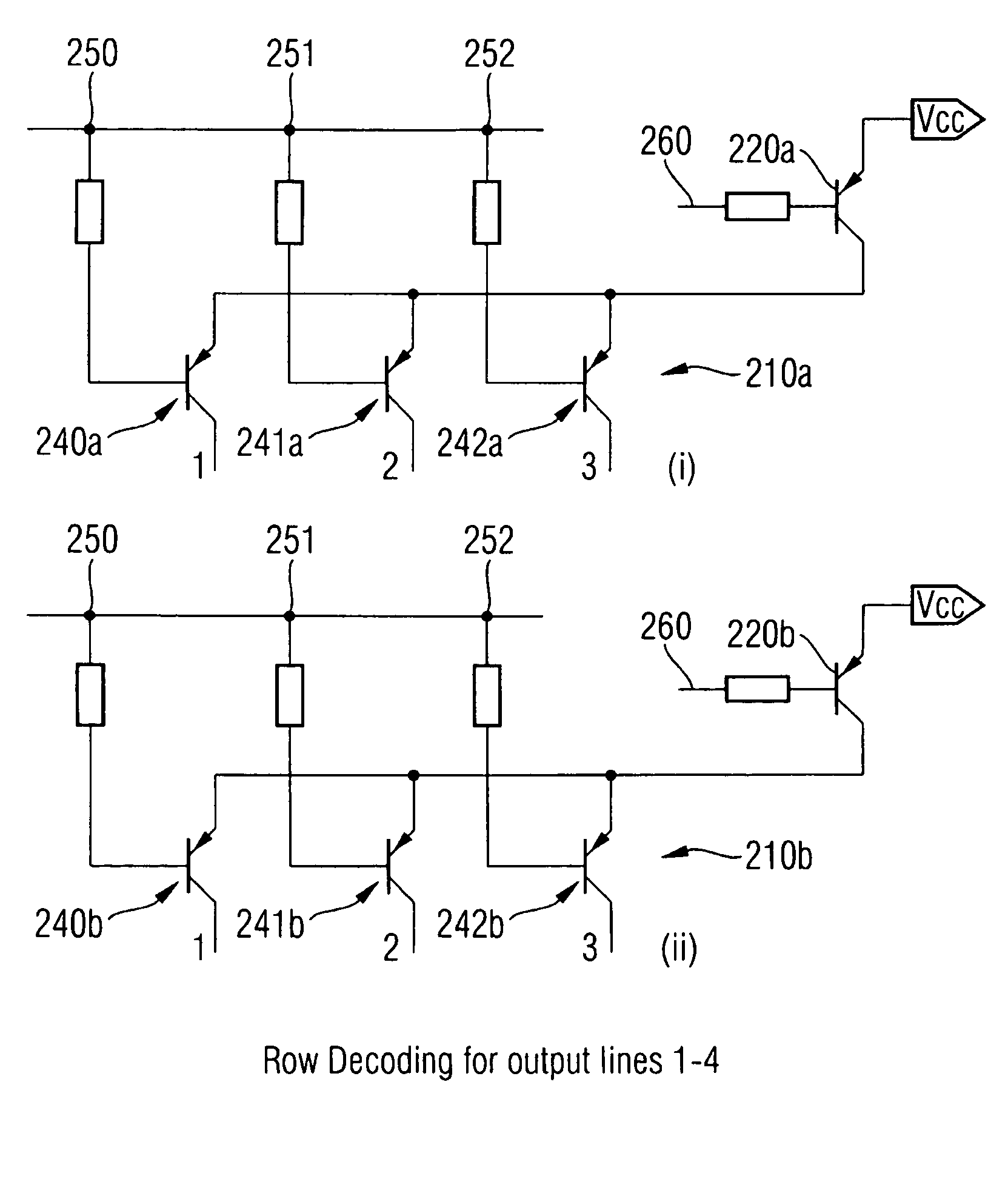
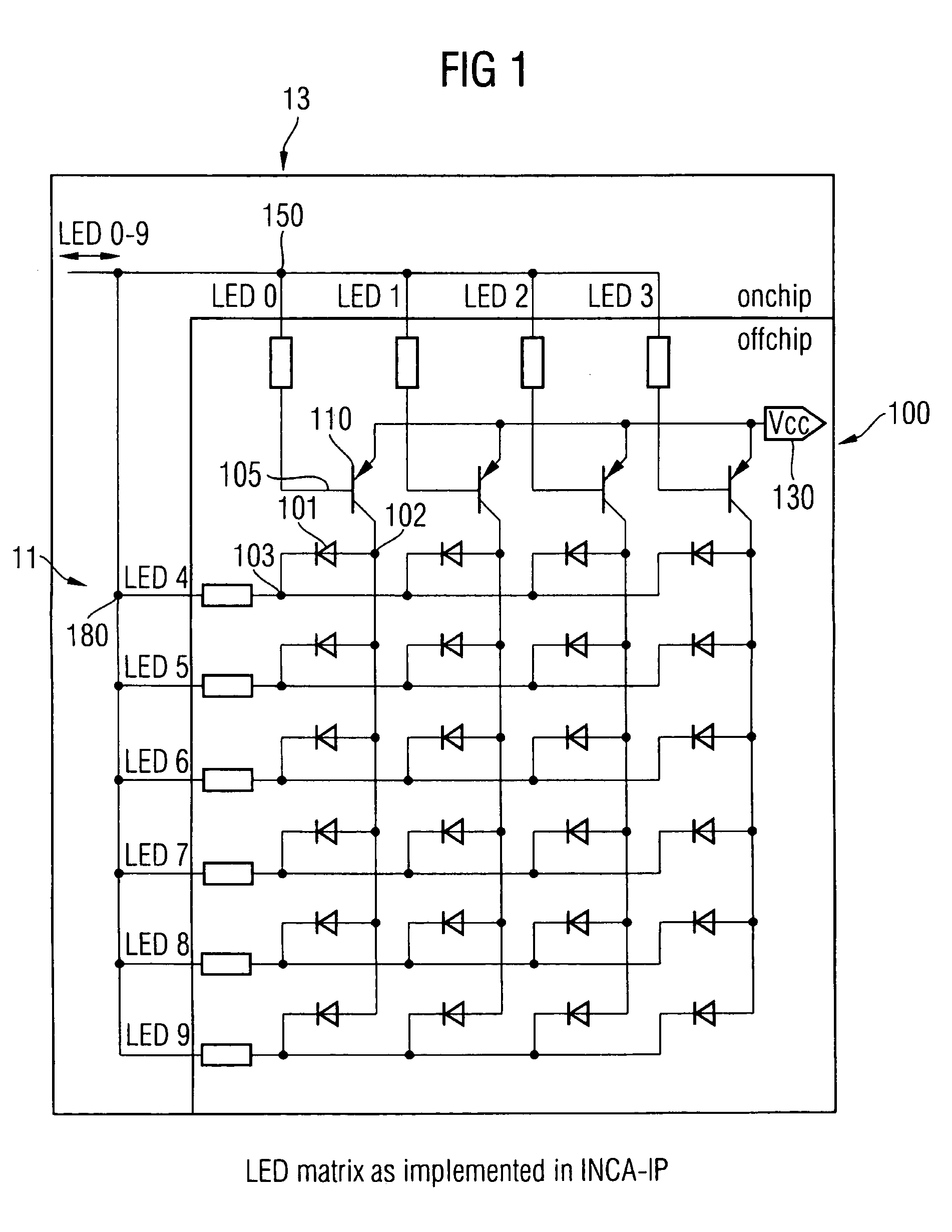
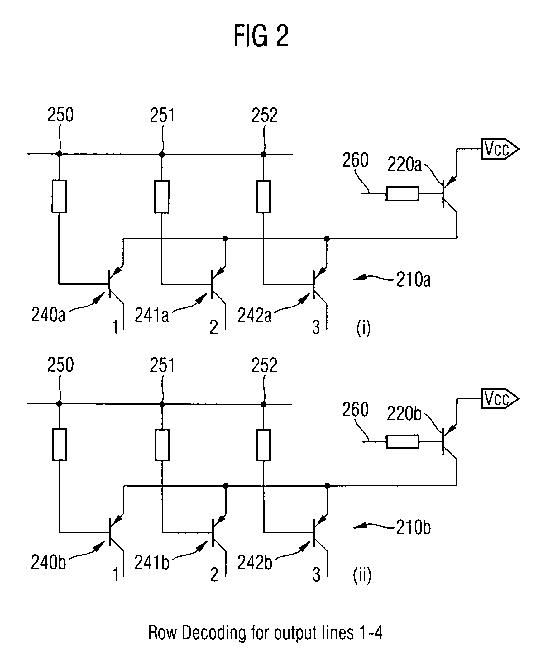
[0015]The present invention increases the number LEDs implemented in the array by using a combination of logical ‘AND’ decoding for the rows and / or columns as well as time division multiplexing (TDM) to multiplex the state for each row / column control input. In the conventional implementation of the LED matrix, each column control input or row control input is only able to control one column or row respectively. In the present invention, at least one of the row / column control inputs is coupled to more than one row / column. Logical ‘AND’ decoding during time division activation of the control inputs is then used to distinguish which one of the plurality of rows / columns attached to an activated control input is being selected.

Multiplexing

[0016]In a time division multiplex system, each channel is assigned a fixed time slot and sampled in a regular sequence by a multiplexer. When the all channels have been sampled, the sequence starts over with the first channel. Thus samples from a parti...


PUM


Abstract

An LED array arrangement that reduces the number of control inputs needed to operate it is described. The reduction in the number of control pins is achieved through the use of logical ‘AND’ decoding and multiplexing of the control input signals.

Description

FIELD OF THE INVENTION[0001]The present invention relates generally to LED arrays. In particular, the invention relates to improved implementation of LED arrays.BACKGROUND OF THE INVENTION[0002]LEDs (light emitting devices) are used in a wide variety of electronic devices as a display for example, to convey information about the status of a device or as a monitor. The various types of LEDs include organic LEDs, semiconductor LEDs and liquid crystal displays. FIG. 1 shows a conventional arrangement 100 for a plurality of LEDs. The LEDs are arranged as a matrix with the plurality of LEDs connected in rows 11 and columns 13. An LED 101 of the matrix comprises a first terminal 102 and a second terminal 103 (e.g. an anode and a cathode). The first terminal 102 of each LED 101 in a column 13 are connected together and coupled to a column control input 150 while the second terminal 103 of each LED in a row 11 are connected together and coupled to a row control input 180. In order to enable...

Claims


Application Information

Patent Timeline
Patent Type & Authority Patents(United States)
IPC IPC(8): G09G3/32G09F9/33H01L21/00H01L29/18
CPCG09G3/32G09G2310/0275G09G2310/0267G09G3/3208
Inventor LIM, SWEE HOCK ALVINNARANG, JASMEET SINGH
Owner LANTIQ BET GMBH & CO KG
Why Eureka
Try Eureka