
Image processing apparatus and method using image information and additional informational or an additional pattern added thereto or superposed thereon

a processing apparatus and image information technology, applied in the field of image processing apparatus, can solve the problems of unable to trace an illegally used copying apparatus or its operator from the illegal copies made therefrom, and the number of image patterns to be registrable in this circuit is limited

Inactive Publication Date: 2006-06-06
CANON KK
View PDF72 Cites 6 Cited by
  • Summary
  • Abstract
  • Description
  • Claims
  • Application Information

AI Technical Summary

Benefits of technology

[0015]It is an object of the present invention to provide an image processing apparatus capable of adding a least noticeable pattern when information for specifying a copying machine or person is to be added to a reproduced image of an original image.
[0017]It is still another object of the present invention to provide an image processing apparatus capable of realizing an arrangement which satisfies both modulation / demodulation and pattern addition.
[0019]It is still another object of the present invention to provide an image processing apparatus capable of preventing the above loophole.
[0021]It is still another object of the present invention to provide an image processing apparatus capable of adding a pattern regardless of changes in environmental recording conditions.
[0025]It is still another object of the present invention to provide an image processing apparatus capable of easily detecting a pattern representing a machine number or the like.

Problems solved by technology

In recent years, the improvements in the performance of color copying machines and color printers have been so great that, they may be successfully used in illegal applications.
It is almost impossible to trace an illegally used copying apparatus or its operator from the illegal copies made therefrom.
The number of image patterns to be registrable in this circuit is limited.
It is, therefore, impossible to register all kinds of originals to be discriminated.
Moreover, in a color copying machine or printer having an external interface, such a circuit for determining a specific original, may not properly function.
It is very difficult to even identify and detect a specific original, and the number of images of determinable specific originals is limited.
In addition, when image data for expressing the respective color components are surface-sequentially sent in units of colors, image data must be stored in a memory to perform the identification, which results in the use of a high cost memory, thereby requiring a high cost for identifying a specific original.
Even if the number if specific originals as target objects is limited to the number of recognizable objects, a picture very similar to a registered specific original may be erroneously determined, or a stained specific original may be erroneously determined not to be a specific original.
It is impossible to avoid such an error.
When an original which is not supposed to be copied is copied, it is important to specify the illegally used copying machine or its operator because the detection capability for identifying specific originals is limited.
In particular, for example, in a color copying machine used in the fields of design, a problem is posed when a pattern which is not present in an original is noticeable on a reproduced image.
In copying an original, image signals are not necessarily uniform due to variations in sensitivities of a CCD sensor even if a uniform color original is used.

Method used


Image

  • Image processing apparatus and method using image information and additional informational or an additional pattern added thereto or superposed thereon
  • Image processing apparatus and method using image information and additional informational or an additional pattern added thereto or superposed thereon
  • Image processing apparatus and method using image information and additional informational or an additional pattern added thereto or superposed thereon

Examples


first embodiment

[General Description of Apparatus]

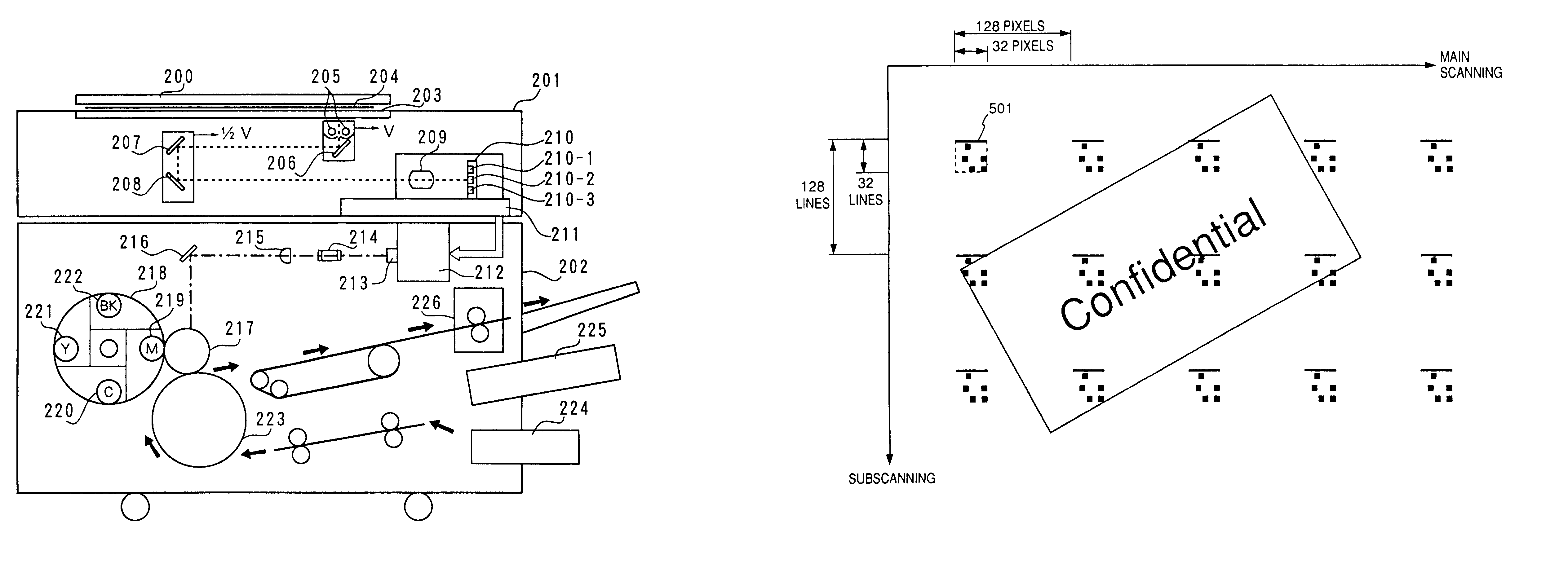
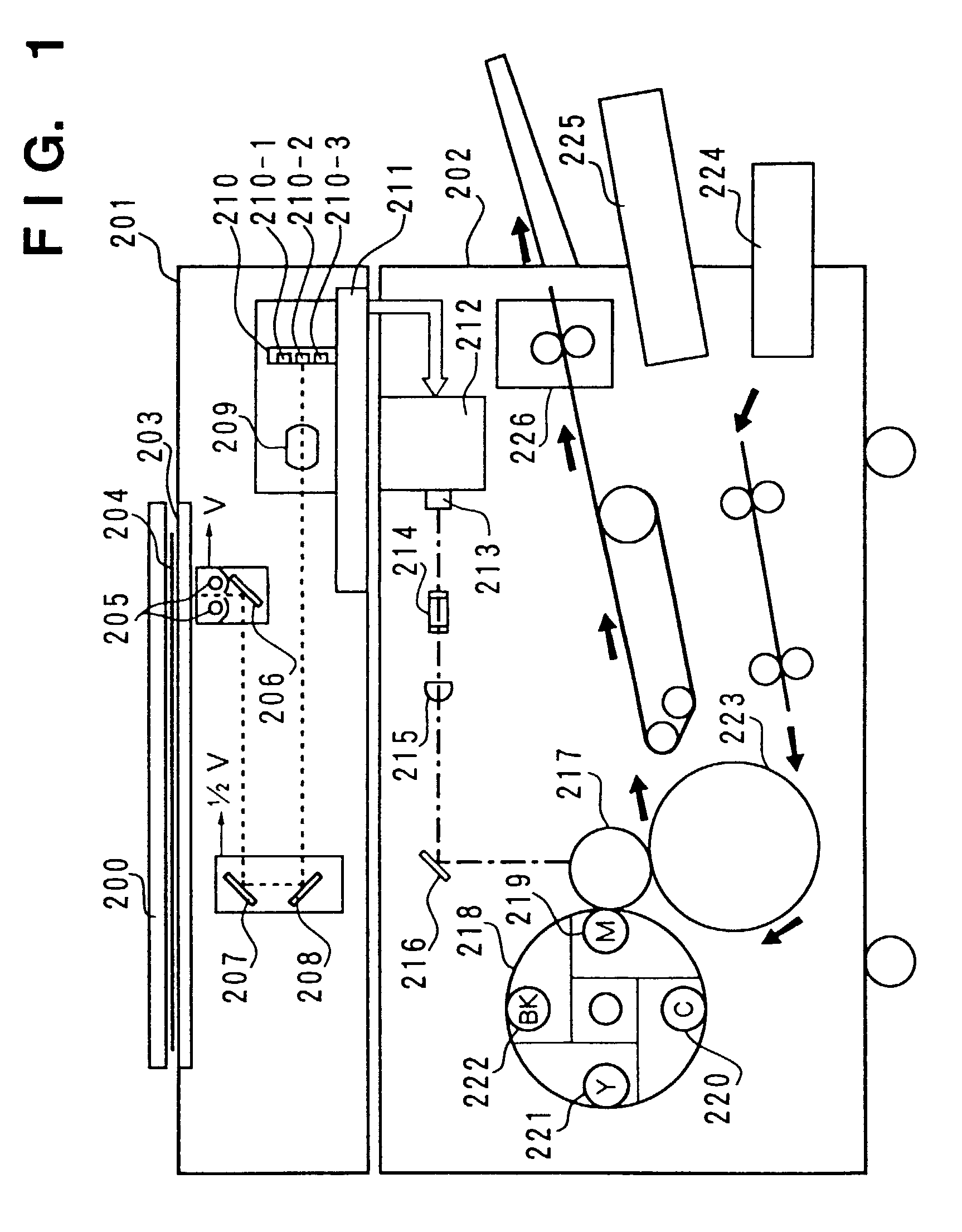
[0079]FIG. 1 is a side sectional view showing the internal arrangement of a color copying machine according to the first embodiment of the present invention. Referring to FIG. 1, reference numeral 201 denotes an image scanner for reading an original at a resolution of 400 dpi (dots / inch) and processing digital signals. Reference numeral 202 denotes a printer for printing out a full color image, corresponding to the original image read by the image scanner 201, on a sheet at a resolution of 400 dpi.

[0080]In the image scanner 201, reference numeral 200 denotes a mirror surface press plate. An original 204 on an original glass table (to be referred to as a platen hereinafter) 203 is irradiated with a lamp 205. Light reflected by the original 204 is guided to mirrors 206, 207, and 208 and is focused by a lens 209 on a three-line sensor (to be referred to as a CCD hereinafter) 210. The read image signals are sent as full color information, i.e., red (R),...

second embodiment

[0148]The second embodiment of the present invention will be described below.

[0149]FIG. 20 is a view showing the outer appearance of a copying machine according to the second embodiment. The same reference numerals as in the copying machine of the first embodiment denote the same parts in the copying machine of the second embodiment, and a detailed description thereof will be omitted.

[0150]Referring to FIG. 20, reference numeral 111 denotes an interface with an external equipment 228. The interface 111 performs interfacing for a video signal, a sync signal, and a signal used in communication. This interface 111 is connected to the external equipment 228 (e.g., a reader) having the same function as that of an image scanner 201. The interface 111 is also connected to a signal processor 211 through a cable or the like.

[0151]FIG. 21 is a block diagram of the image scanner 201 constituting the copying machine according to this embodiment. The same reference numerals as in the image scann...

third embodiment

[0178]The third embodiment of the present invention will be described below. A copying machine of this embodiment has the same arrangement as that of the first embodiment shown in FIG. 1, and a detailed description thereof will be omitted.

[0179]FIG. 28 is a block diagram for explaining the arrangement of an image scanner 201 according to this embodiment. Referring to FIG. 28, reference numeral 1316 denotes a counter for outputting a main scanning address for designating main scanning positions of line sensors 1301 to 1303 constituting a line sensor 210. That is, if a horizontal sync signal HSYNC is set at logic “1”, the count of the counter 1316 is set to a predetermined value by a CPU (not shown) and is incremented by an image clock signal CLK.

[0180]An image formed on the line sensor 210 is photoelectrically converted by the three line sensors 1301 to 1303 and is extracted as R, G, and B component read signals. These signals are processed through amplifiers (AMPs) 1304 to 1306, sam...


PUM


Abstract

Predetermined additional information is superposed as a dot pattern on image information read by an image scanner, and the image information superposed with the additional information is modulated. The modulated information is demodulated and recorded on a recording medium to perform a series of operations, i.e., to simultaneously satisfy both pattern addition and modulation / demodulation.

Description

[0001]This application is a continuation of application Ser. No. 09 / 993,725 filed Nov. 27, 2001, now pending, which is a divisional of application Ser. No. 08 / 863,468, filed May 27, 1997, now U.S. Pat. No. 6,421,145, which is a continuation of appln. Ser. No. 08 / 126,710, filed Sep. 27, 1993 now abandoned.BACKGROUND OF THE INVENTION[0002]The present invention relates to an image processing apparatus for adding specific information to an input image and outputting the resultant image.[0003]In recent years, the improvements in the performance of color copying machines and color printers have been so great that, they may be successfully used in illegal applications. It is almost impossible to trace an illegally used copying apparatus or its operator from the illegal copies made therefrom.[0004]To prevent illegal copying, the following countermeasure has been attempted. A specific image pattern is registered in a color copying machine or a color printer itself beforehand, and when the pa...

Claims


Application Information

Patent Timeline
IPC IPC(8): H04N1/40H04N1/00H04N1/32
CPCH04N1/00843H04N1/00848H04N1/00867H04N1/32144H04N1/0087H04N2201/3271H04N2201/3205H04N2201/327
Inventor KURITA, MITSURUMAESHIMA, KATSUYOSHIFUNADA, MASAHIROSUZUKI, YASUMICHITAKARAGI, YOICHIKANNO, AKIKOISHIMOTO, KOICHI
Owner CANON KK
Learn More