Navigation system

a technology of navigation system and vehicle, applied in the direction of navigation instruments, traffic control systems, instruments, etc., can solve the problems of difficult parking, inconvenient meeting place for cars, and difficult to meet,

Inactive Publication Date: 2006-06-06
PANASONIC CORP
View PDF10 Cites 45 Cited by
  • Summary
  • Abstract
  • Description
  • Claims
  • Application Information

AI Technical Summary

Benefits of technology

[0018]This structure allows extracting plural meeting-place candidates suitable for its own mobile unit and the other mobile units to meet, then selecting one place from the candidates, so that no inconvenient place for the meeting place is selected. As a result, its own mobile unit and the other mobile units can meet each other at an appropriate place.
[0019]The transmitting means of the present invention provides at least one of map information to the meeting place, route guidance to the meeting place, an expected arrival time, and expected meeting time. This structure allows the related mobile units to arrive exactly at the selected meeting place based on at least one of those information such as map information to the meeting place, route guidance to the meeting place, an expected arrival time, and expected meeting time.
[0020]The present invention extracts meeting-place candidates from adequate meeting places which includes at least one of a station, bus stop, supermarket, convenience store, park, public office, school, shopping mall, cinema complex, parking lot, open space, and intersection. This structure avoids determining an inconvenient place as a meeting place as the conventional system did, and determines a suitable place for cars to meet each other.
[0021]The navigation system of the present invention allows providing adequate meeting places with priorities respectively, and the meeting place determining means selects one place according to the priorities. This structure allows determining a more suitable place for cars to meet each other.

Problems solved by technology

However, the conventional navigation system simply extracts a meeting place to be reached fastest based on the locations of the cars that want to meet each other, so that the meeting place extracted is not always suitable for the cars to meet.
For instance, extracting a road having heavy traffic and difficult to park, a place with no parking lot, or a street jammed with cars as a meeting place is not always fit for cars to meet.

Method used


Image

  • Navigation system
  • Navigation system
  • Navigation system

Examples


exemplary embodiment 1

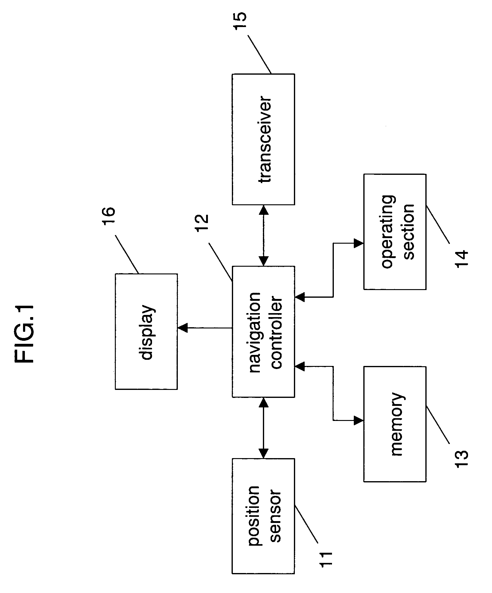
[0033]FIG. 1 shows a schematic block diagram illustrating a navigation system in accordance with the first exemplary embodiment of the present invention. In FIG. 1, position sensor 11 includes a GPS receiver and a self-contained navigation measuring device, and senses a present self-position before supplying it to navigation controller 12.

[0034]Memory 13 is formed of a CD-ROM or a DVD-ROM for storing map information and candidates for a meeting-place. The map information and the candidates stored in memory 13 are read out when necessary, and supplied to navigation controller 12 following the control of controller 12.

[0035]Operating section 14 is used for inputting information such as a destination, transit place, and a variety of instructions. Both of the information and the instructions input through operating section 14 are supplied to navigation controller 12.

[0036]Transceiver 15 obtains service information of trains and buses, information of traffic jam on roads (including infor...

exemplary embodiment 2

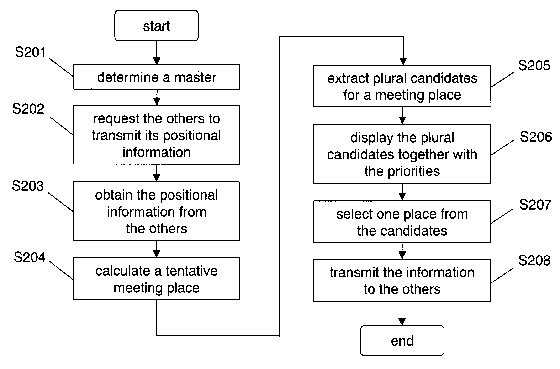
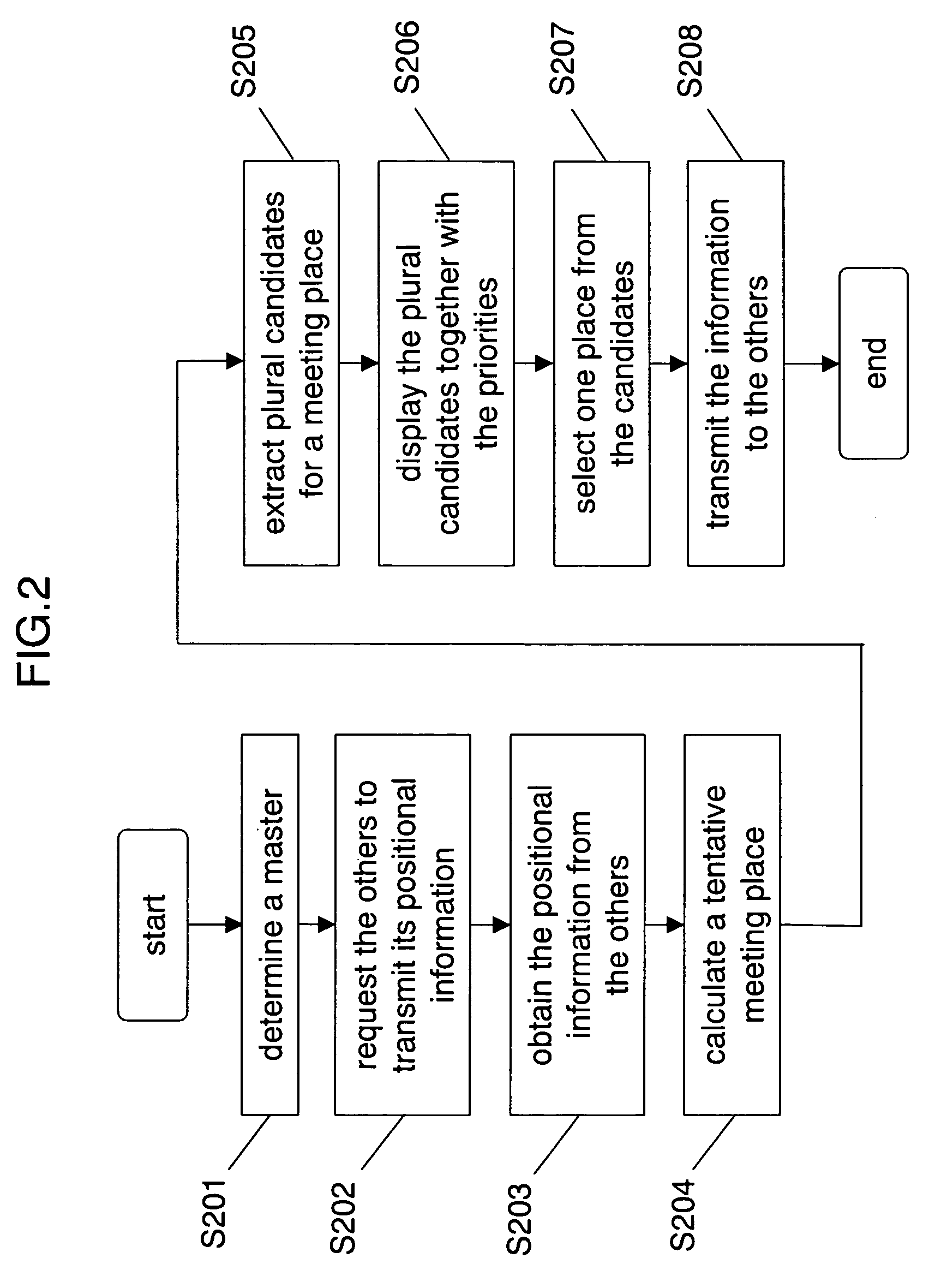
[0096]The second embodiment is demonstrated with reference to FIG. 3, which shows a flowchart illustrating an operation of the navigation system in accordance with the second embodiment.

[0097]The second embodiment differs from the first one in the following point: An input of a destination or a transit place on the way to the destination through operating section 14 allows displaying the map information and route guidance to the destination or the transit place on display 16. The meeting place fastest to arrive is calculated taking into account the destination or the transit place.

[0098]In FIG. 3, step 301–step 303 are similar to step 201–step 203 shown in FIG. 2. Navigation controller 12 obtains present locations of the other parties that want to meet each other (S303). Then controller 12 checks whether or not the destination (hereinafter including the transit place) is already input (S304). If the destination is not yet input, a fastest reachable meeting place is calculated based ...

exemplary embodiment 3

[0105]The third exemplary embodiment is demonstrated hereinafter with reference to FIG. 4, which shows a flowchart illustrating an operation of the navigation system in accordance with the third embodiment of the present invention.

[0106]The third embodiment differs from the first and the second ones in adding steps 401–405 after step 207 and step 309 of the first and the second embodiments.

[0107]To be more specific, after the selection of one place from the plural candidates (S207, S309), the map information and route guidance are transmitted together with the name of the selected one to each one of the other parties (S401). If the selected one is unfavorable for one of the other parties, the one of the other parties transmits a desirable meeting place to the master itself (S402).

[0108]Based on a new meeting place transmitted from one of the other parties, the master itself determines whether or not it is necessary to change the meeting place (S403), and inputs the determination thr...


PUM


Abstract

A navigation system, which can determine a place suitable for meeting as a meeting place, is disclosed. This navigation system obtains positional information of mobile units, and extracts candidates for a meeting place from adequate meeting places registered in advance. The navigation system automatically selects or a user manually selects one place from the extracted candidates, and determines the selected one as the meeting place. The navigation system transmits the information about the meeting place to the other mobile units, so that the mobile units can meet each other at the right meeting place free from any place-caused inconvenience.

Description

[0001]This application is a U.S. National Phase Application of PCT Interntional Application PCT / JP02 / 10646.TECHNICAL FIELD[0002]The present invention relates to a navigation system which can set a meeting place for a plurality of mobile units to meet each other with ease.BACKGROUND ART[0003]A navigation system, which sets a meeting place automatically and quickly, has been available for users who drive their cars to meet each other by communicating with each other using in-car navigation devices installed.[0004]An instance of the foregoing navigation system is disclosed in Japanese Patent Application Non-Examined Publication No. 2000-88591. This system sets automatically a meeting place for the cars to meet each other in the fastest way taking into account the information such as a cruising speed of each car and traffic jam on the road.[0005]In the foregoing conventional structure, the respective navigation devices, installed in the cars that want to meet each other, measure their o...

Claims


Application Information

Patent Timeline
Patent Type & Authority Patents(United States)
IPC IPC(8): G01C21/20G01C21/00G09B29/00G01C21/26G01C21/34G01S19/02G01S19/48G08G1/005G08G1/09G08G1/0969G08G1/127G09B29/10
CPCG01C21/3438G08G1/127G08G1/0969G01C21/3685
Inventor SAIKI, MASAHIRO
Owner PANASONIC CORP
Why Eureka
Try Eureka