
Landscaping device with protective function on landscape plants and working method of landscaping device

A landscaping and working method technology, applied in the field of landscaping, can solve the problems of effective protection, death, and poor growth of plants that cannot be viewed, and achieve the effect of reducing the stimulation of wind, rain and strong light

Active Publication Date: 2018-09-28
福建坤加建设有限公司
View PDF9 Cites 1 Cited by
  • Summary
  • Abstract
  • Description
  • Claims
  • Application Information

AI Technical Summary

Problems solved by technology

[0004] However, the existing landscaping is relatively fixed and cannot effectively protect the viewing plants. For example, some plants are light-sensitive or water-sensitive plants. If they are exposed to strong light for a long time or in a precipitation environment for a long time, they will Can cause poor growth or even death of plants

Method used


Image

  • Landscaping device with protective function on landscape plants and working method of landscaping device
  • Landscaping device with protective function on landscape plants and working method of landscaping device
  • Landscaping device with protective function on landscape plants and working method of landscaping device

Examples


no. 1 example

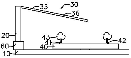
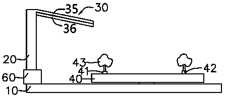
[0030] Such as figure 1 with figure 2 As shown, the landscaping device with protective properties for landscape plants of this embodiment includes a base 10, a support rod 20, a shielding member 30 and a bearing member 40.

[0031] The support rod 20 is arranged on the base 10, and the support rod 20 is connected to the base 10 through a lifting assembly 60, and the lifting assembly 60 can drive the support rod 20 to move in the vertical direction. The lifting assembly 60 may specifically include a motor and a ball screw rod. The motor provides power, and the screw rod moves in the vertical direction, thereby driving the support rod to lift in the vertical direction. In addition, the lifting assembly 60 may also be a hydraulic cylinder, which realizes the vertical lifting of the support rod 20 in a hydraulic manner.

[0032] The shield 30 is connected to the support rod 20, and the shield 30 forms a shielding area on the base 10. The shield 30 includes a first extension section 3...

no. 2 example

[0039] This embodiment is basically the same as the above-mentioned first embodiment, and only the differences will be described in detail below.

[0040] Such as Figure 4 As shown, the base 10 of this embodiment includes a substrate 11, a rotating body 12, and a placing member 13. The rotating body 12 includes a disc 14 and a protrusion 15. The protrusion 15 is arranged on the disc 14, and the center of the placing member 13 is 16 is rotatably connected to the substrate 11, the placing member 13 has a plurality of grooves 17, and the protrusions 15 can be inserted into the grooves 17 to drive the placing member 13 to rotate. When the disc 14 is in a rotating state ( image 3 The middle means clockwise rotation), the protrusion 15 gradually enters the first groove 171, the disk 14 continues to rotate, and the protrusion 15 drives the placing part 13 to rotate, so that the placing part on the placing part 13 moves from the first position To the second position. The disc 14 conti...

no. 3 example

[0043] Such as Figure 5 As shown, this embodiment is basically the same as the above-mentioned first embodiment, and only the differences will be described in detail below.

[0044] The carrier 43 of this embodiment has a containing body 47 for recovering rainwater. The containing body 47 is arranged between the first placement portion 41 and the second placement portion 42; the external rainwater flows in along the inclined shield 30 Into the containing body 47, the containing body 47 has a cover 48 which is in an open state when receiving rainwater, and is in a closed state when the cover 48 is in a rainwater storage state.


PUM


Abstract

The invention provides a landscaping device with a protective function on landscape plants. A placement part can move into or out of a shielding area; when the placement part is located inside the shielding area, the landscape plants can be protected, and therefore the stimulation of wind, rain and strong light on the landscape plants is reduced; when the landscape plants are located outside the shielding area, the landscape plants can soak up the sun or enjoy the irrigation of natural rainwater. In addition, a lifting assembly can drive a supporting rod to rise and fall in the vertical direction, the requirement for placement of the landscape plants at different heights is met, and it is avoided that the landscape plants are too high and cannot be placed in the shielding area. In addition, a first extension section and a second extension section can be in an unfolded state and a folded state respectively, and the size of the shielding area is adjusted according to different requirements.

Description

Technical field [0001] The technical field involved in the present invention belongs to the field of landscaping, and particularly relates to a landscaping device with protective properties for landscape plants and a working method thereof. Background technique [0002] Landscaping is a beautiful natural environment and recreational area created by the use of engineering technology and artistic means in a certain area, by means of terrain transformation (such as building rockery, overlapping stones, water conservancy arrangement), planting flowers and plants, building buildings and laying out garden roads, etc. , It is called garden. [0003] Gardens are, for example, home gardens, small amusement gardens, gardens, gardens, parks, etc. With the development of gardening disciplines, from a broad perspective, it also includes forest parks, scenic spots, nature reserves or national parks and recreational resorts. [0004] However, the existing landscaping is relatively fixed and canno...

Claims


Application Information

Patent Timeline
Patent Type & Authority Applications(China)
IPC IPC(8): A01G13/02
CPCA01G13/0206
Inventor 赵佳丽
Owner 福建坤加建设有限公司
Learn More